Service hotline
+86 0755-23615795
 en
en Release date:2025-04-23Author source:KinghelmViews:1851
In brief, an RF connector (radio-frequency connector) is an electrical interface designed to transmit high-frequency signals—typically 300 MHz to tens of GHz—while preserving the coaxial cable’s shielding and impedance characteristics to minimize signal loss and reflection. These connectors feature precision mechanical designs (threaded, bayonet, blind-mate, etc.) and careful impedance matching to ensure signal integrity in applications ranging from Wi-Fi antennas and satellite communications to radar and test instrumentation. Numerous standardized types (SMA, N-Type, 2.92 mm, 1.85 mm, etc.) serve different frequency ranges and power levels, making RF connectors indispensable components in modern RF and microwave systems.
An RF connector is an electrical connector engineered for use at radio frequencies, typically from multi-megahertz up to tens of gigahertz. Its primary purpose is to maintain the coaxial cable’s characteristic impedance and shielding at the connection interface to prevent electromagnetic interference and minimize return loss . Mechanically, RF connectors employ fastening mechanisms—such as threaded interfaces (SMA, N-Type), bayonet locks (BNC), or blind-mate springs—that ensure low-ohmic contact and high mating cycles without degrading the gold-plated surfaces .
At microwave frequencies, even small impedance mismatches can cause significant signal reflection, reducing forward power and increasing VSWR (voltage standing-wave ratio). High-quality RF connectors are precision-machined to a nominal impedance (usually 50 Ω or 75 Ω) with tight tolerances, ensuring seamless transmission line continuity and optimal insertion loss performance .
RF connector types are standardized to cover specific frequency bands and applications:
SMA (SubMiniature A): Threaded 50 Ω interface up to 18 GHz; common for Wi-Fi and cellular test gear .
N-Type: 50 Ω threaded connector up to 11 GHz (and precision N up to 18 GHz), used in outdoor and high-power applications .
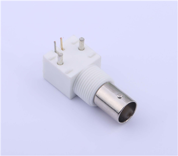
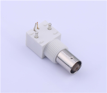
BNC (Bayonet Neill–Concelman): 50 Ω or 75 Ω bayonet lock up to ~4 GHz, prevalent in test equipment and CCTV .
2.92 mm (K-type): Precision connector up to 40 GHz, bridging the gap between SMA and 2.4 mm .
2.4 mm & 1.85 mm: Multi-gigahertz precision connectors up to 50 GHz and 65 GHz respectively, for millimeter-wave systems .
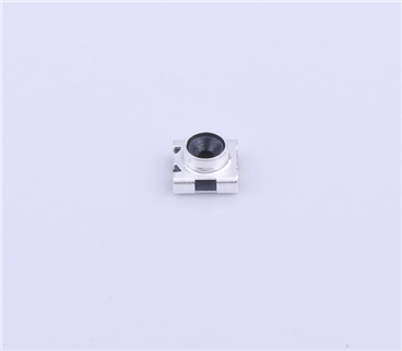
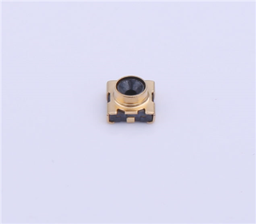
Additional variants—MCX/MMCX/SMP for board-to-cable, TNC for rugged bayonet use, and BMA for blind-mate rack applications—further demonstrate the diversity of RF connector designs .
RF connectors enable reliable signal interconnect in:
Telecommunications: Base stations, small cells, and indoor DAS (Distributed Antenna Systems) .
Satellite & Aerospace: Low-loss feedlines for uplink/downlink and RF test benches .
Radar & Defense: High-power, vibration-resistant connectors in airborne and land-based radar systems .
Test & Measurement: Laboratory analyzers, signal generators, and network analyzers rely on precision connectors for repeatable results .
Consumer Electronics: Removable Wi-Fi/Cellular antennas on routers and PCIe cards often use SMA or RP-SMA connectors .
Key criteria when choosing an RF connector include:
Frequency Range: Ensure connector <sup>–3 dB</sup> bandwidth exceeds system frequency .
Impedance: Match cable and component impedance (50 Ω vs. 75 Ω) to prevent VSWR spikes .
Power Handling: Higher power connectors (N-Type, 2.92 mm) feature robust dielectric and contact designs .
Mechanical Durability: Mating cycles and environmental sealing (IP-rated N-Types for outdoor use) matter for field applications .
Size & Mounting: Board-level (MMCX, SMP) vs. bulkhead (SMA, N-Type) variants accommodate different form factors .
RF connectors are the linchpins of any high-frequency system, ensuring that sensitive microwave signals traverse cables and devices with minimal loss, reflection, and interference. By understanding impedance matching, mechanical styles, and frequency ratings, engineers can select the optimal connector type—whether SMA for Wi-Fi test setups, 2.92 mm for millimeter-wave research, or N-Type for rugged, high-power links—to achieve reliable RF performance.
