Service hotline
+86 0755-23615795

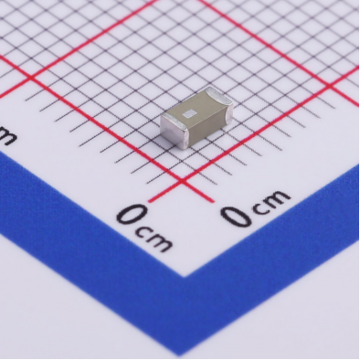
Release date:2025-08-06Author source:KinghelmViews:174
Bluetooth SMD (Surface Mount Device) antennas are compact (typically 5mm × 10mm) and fragile (ceramic substrates make up ~60%), making them prone to breakage from drops, collisions, or improper soldering. When damaged, you may experience severe signal degradation (e.g., transmission range drops from 10m to 2m), frequent disconnections, or complete signal loss. This guide covers the 3 common breakage types, repair methods, replacement process, and prevention tips to help you quickly restore device communication.
The structure of a Bluetooth SMD antenna means that breakage location significantly affects how it should be handled. Blind repair attempts may cause further damage:
Symptoms: The feed point (center solder joint) or ground pad detaches from the PCB. The antenna body (radiator and substrate) remains intact. You may see a visible gap between pad and antenna.
Repair Feasibility: High (simply resoldering is usually enough without performance loss).
Typical Cause: Drop impact or overheating during soldering that melts solder joints.
Symptoms: For antennas with external feed lines (e.g., IPEX types), the cable breaks near the antenna base. You’ll see bend marks and exposed inner copper wire.
Repair Feasibility: Medium (requires re-soldering; thin wires may break again).
Risk: Feed line impedance is 50Ω; improper soldering can raise impedance to 70Ω, increasing signal loss by 30%.
Symptoms: The antenna body (ceramic or FR4 substrate) is cracked, copper radiator torn, or a full-depth crack is present (flexing reveals looseness).
Repair Feasibility: None (damage causes impedance mismatch, VSWR >3.0, blocking radiation).
Typical Cause: Physical pressure (e.g., crushing) or overheating above 85℃, causing ceramic brittleness.
Essential Tools:
Temperature-controlled soldering iron (set to 300–350℃; for ceramic, ≤320℃);
Flux (rosin or no-clean type to remove oxidation and ensure <0.1Ω joint resistance);
Fine solder wire (diameter 0.3mm to prevent overflow);
Magnifier (3–5× to inspect 0603-sized pads);
Anti-static wrist strap (essential in dry environments to avoid ESD damage).
Work Environment:
Use an insulated surface (e.g., wooden table), keep away from metals and airflow (e.g., fans) that could shift solder before it solidifies.
Step 1: Clean Old Solder
Gently melt and remove residual solder using a soldering iron and desoldering braid. Avoid scraping to prevent pad lift. Expose clean copper (≥0.5mm² area).
Step 2: Align Antenna
Precisely align the antenna feed point with the PCB pad (misalignment ≤0.2mm). Use tweezers to hold it steady.
Step 3: Tack Solder
Apply minimal solder (covering ~50% of pad area). Briefly touch the joint with the iron (≤1s) to form a cone-shaped joint (~0.3–0.5mm height).
Step 4: Re-solder Ground Pads
If ground pads are detached, solder at least two points to maintain <0.1Ω ground resistance. Use a multimeter in continuity mode (red probe on antenna ground, black on PCB ground — beep = good).
Step 1: Trim & Strip Wire
Cut off the broken section, keeping ~5mm cable. Carefully strip insulation to expose 0.5mm of copper wire without damaging strands.
Step 2: Tin the Wire & Pad
Pre-tin both the copper wire and antenna pad with solder to improve joint quality and reduce oxidation.
Step 3: Re-solder Joint
Align wire and pad. Heat from the side (don’t touch antenna base directly). As solder melts, gently press wire into place. Soldering time ≤1.5s.
Step 4: Insulate the Joint
Use heat shrink tubing (1mm diameter), shrink at ~120℃. Alternatively, apply a small amount of hot glue (<0.5mm thickness).
Continuity Test:
Use a multimeter to test between feed point and Bluetooth RF output. Resistance should be >100kΩ (open circuit). <10Ω indicates a short — clean and rework needed.
Signal Strength Test:
Use the “BLE Scanner” app:
RSSI at 1m should be ≥-65dBm (if previously -90dBm, gain ≥25dB is acceptable);
Transfer 1000 packets (20 bytes each); packet loss should be ≤1%. If higher, check solder joints.
If the radiator or substrate is broken, replacement is the only option. Poor antenna selection or installation can reduce signal strength by 30%. Follow this strict process:
Key Parameters:
Dimensions: Measure original length × width (e.g., 10mm×8mm); new antenna must be within ±1mm.
Interface / Pads: Count ground pads (usually 2–4 for soldered types) or confirm connector type (e.g., IPEX U.FL, MMCX for snap-on).
Frequency Band: Must support 2.4–2.485GHz (look for “Bluetooth Only” or “2.4GHz Omni”).
Where to Find Specs:
Check user manuals, antenna silkscreen (e.g., “BT-2400-1010” = 2.4GHz, 10×10mm), or contact the device manufacturer.
Material Matching:
Original ceramic? Use the same (dielectric mismatch causes frequency shift).
Flexible device (e.g., smart band)? Use FPC antennas (bend radius ≥1mm).
Harsh environments (-40~85℃)? Choose high-temp materials (e.g., LCP, temp coeff <±10ppm/℃).
Avoid Cheap Pitfalls:
Low-cost antennas (<¥5) often skip impedance matching, resulting in VSWR >2.0. Choose models marked “Impedance: 50Ω ±5Ω”.
Soldered Type: Use iron to melt solder points individually (each ≤2s to avoid pad lift). Add flux if solder is hardened.
Snap-On Type: Use tweezers to pull connector straight upward (don’t yank cable — risk PCB damage).
Cleanup: Wipe area with alcohol swab to remove old solder or glue residue.
Soldered Type:
Align feed point and pad precisely (<0.1mm misalignment). Solder feed point first, then ground pads to avoid tilt.
Use solder that covers ~80% of pad (too much lowers impedance, too little causes bad contact).
Snap-On Type:
Press down until a “click” is heard. Perform a light pull test — connection should remain firm.
Use cable ties to secure feed line ~5cm from connector to prevent vibration-related disconnection (important for automotive/industrial use).
Use Bluetooth testing apps (e.g., nRF Connect):
RSSI at 1m: ≥-60dBm (Excellent), -60~-75dBm (Good), < -80dBm (Poor).
At 10m, signal drop should be ≤20dB (e.g., -60 → -80dBm). If worse, check antenna orientation (omni antennas must lie flat), and remove nearby metal (keep ≥30cm away).
Installation Protection: Add 3mm-high silicone bumpers around antenna (e.g., inside case) to absorb drop shocks.
Cable Fixing: Secure feed lines every 10cm with adhesive to reduce bending stress (extends lifespan from 30 to 100 insertions).
Temperature Control: Keep soldering below 350℃, ≤2s per joint (ceramic ≤320℃).
Avoid Pressure: Don’t stack heavy items during storage — ceramic antennas only resist ~50N (≈5kg) before cracking.
Periodic Checks: For industrial equipment, inspect solder joints under a magnifier every 3 months. Resolder if cracks are found.
Design for Durability: Choose "integrated" antennas in new designs (no solder points, 50% better vibration resistance).
When a Bluetooth SMD antenna breaks, first identify the failure type. Solder pad or feed line issues are often repairable (50–80% success rate), while radiator/substrate damage requires replacement. Follow proper soldering and impedance-matching techniques during repairs, and match specifications strictly for replacements.
If issues persist after repair (e.g., >5% packet loss), the device's RF circuit may be damaged — seek professional diagnosis instead of wasting resources on antennas. With proper protection, antenna lifespan can increase 2–3× and reduce future breakage risk.


Copyright © Shenzhen Kinghelm Electronics Co., Ltd. all rights reservedYue ICP Bei No. 17113853
