Service hotline
+86 0755-23615795

Release date:2025-08-08Author source:KinghelmViews:1204
The specifications of board-to-board connectors directly determine whether they can meet device requirements. For example, a medical device experienced unstable mating and a 40% increase in repair rate because of a wrong pin pitch selection (0.5mm was mistakenly replaced with 0.8mm); an industrial robot encountered connector loosening and downtime after six months due to ignoring vibration specifications (insufficient resistance at 100Hz). This article systematically breaks down 12 key specifications of board-to-board connectors (electrical, mechanical, environmental) with an attached scenario compatibility table to help you avoid 90% of specification mismatches.
I. Electrical Specifications: Core Indicators for Signal Transmission
Electrical parameters directly affect the connector’s conductivity and signal integrity and are key for high-speed, high-power applications.
1. Rated Current (Current Carrying Capacity)
Definition: The maximum continuous current a single pin can carry under ambient temperature of 25℃. Common specs include 0.5A, 1A, 2A, 3A, and 5A.
Key Rule: Current capacity correlates positively with pin cross-sectional area (0.3mm² supports 2A, 0.5mm² supports 3A) and decreases as temperature rises — at 85℃, rated current drops to 70% of room temperature value (e.g., 3A → 2.1A).
Application Scenarios:
Low current (≤1A): Sensors, camera modules (e.g., front camera connectors on smartphones rated at 0.5A)
Medium current (1-3A): Motherboard to display (e.g., 2A backlight power transmission on tablets)
High current (≥5A): Industrial power boards (e.g., 5A power interfaces in PLC control cabinets)
2. Contact Resistance
Definition: Resistance at the contact points of pins; high-quality connectors have initial contact resistance ≤20mΩ, which should remain ≤50mΩ after 500 insertions/removals.
Testing Standard: IEC 60512, measured with 100mA current to avoid Joule heating, with batch deviation ≤10mΩ.
Risk Warning: Contact resistance >100mΩ causes signal attenuation (e.g., 30% loss for 100Mbps signals), often due to pin oxidation or poor contact.
3. Insulation Resistance
Definition: The insulation ability between adjacent pins, required ≥1000MΩ at room temperature (tested at 500V DC), and ≥100MΩ in humid environments (95% RH).
Failure Consequence: Insulation resistance <100MΩ may cause signal crosstalk (e.g., HDMI and USB signal interference), potentially leading to short circuits and device damage.
4. Dielectric Withstand Voltage
Definition: Maximum AC voltage the connector pins or between pins and housing can withstand for 1 minute without breakdown; common ratings include 500V AC and 1000V AC.
Safety Margin: Operating voltage should be ≤70% of rated voltage (e.g., 500V rated connectors recommended for ≤350V use); medical devices require 50% margin for electrical safety.
5. Transmission Rate and Impedance
Key parameters for high-speed signals:
Differential Impedance: Should be controlled at 90Ω ±10% (USB 3.0/4.0) or 50Ω ±10% (RF signals).
Transmission Rate: Connectors with 0.8mm pitch support ≤5Gbps, 0.5mm pitch up to 10Gbps, and 0.4mm pitch up to 20Gbps (e.g., PCIe 5.0 devices).
Test Method: Time Domain Reflectometry (TDR) used to measure impedance continuity with fluctuations ≤15% to ensure no signal reflection.
II. Mechanical Specifications: Physical Parameters Affecting Connection Reliability
Mechanical specs determine installation accuracy, mating durability, and vibration resistance—critical for industrial and automotive applications.
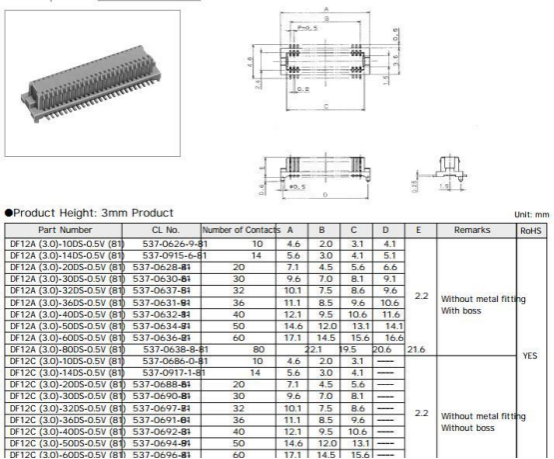
1. Pin Pitch
Common specs: 0.4mm, 0.5mm, 0.8mm, 1.0mm, 1.27mm, 2.54mm, with precision tolerance ≤±0.05mm to avoid mating misalignment.
Selection Formula: Pitch = (PCB trace width + trace spacing) × 2; for example, a phone motherboard with 0.15mm trace width and 0.15mm spacing suits a 0.6mm pitch (select standard 0.5mm).
Typical Uses:
0.4–0.5mm: Smartphones, smartwatches (space-constrained, require SMT precision soldering)
0.8–1.0mm: Tablets, routers (balance density and manufacturability)
2.54mm: Industrial control cabinets (easy manual soldering, good maintainability)
2. Stack Height
Definition: Distance between two PCB boards after connector mating; ranges from 1.5mm to 30mm, common sizes include 5mm, 8mm, 10mm, 15mm.
Key Requirement: Height tolerance ≤±0.2mm (e.g., 10mm spec should be 9.8–10.2mm) to prevent overly tight mating or poor contact.
Measurement: Use micrometer at four connector corners, average values to ensure compatibility with reserved space (recommended 0.5mm margin).
3. Insertion/Extraction Cycles (Durability)
Standard specs: 30, 50, 100, 500, 1000 cycles (tested per IEC 60512, with ≤30% contact resistance change post cycles).
Material Influence: Gold plating thickness affects durability — 1μm gold supports ~100 cycles, 3μm gold can reach 500 cycles (automotive grade requires ≥500 cycles).
Application Scenarios:
Low frequency (≤30 cycles): Disposable medical devices (e.g., single-use monitor mainboards)
Medium frequency (100–500 cycles): Consumer electronics (e.g., connectors during smartphone repairs)
High frequency (≥1000 cycles): Industrial test equipment (frequent module swapping)
4. Insertion/Extraction Force
Range: Single pin insertion force 2–30N, extraction force 0.5–10N; uniformity across pin row required (deviation ≤20%).
Risks: Excessive insertion force (>30N) may deform PCB; too low extraction force (<0.5N) weakens vibration resistance (risk of detachment in automotive use).
Test Standard: Use force gauge for steady-speed insertion/removal (25mm/min), record peak force and deviation.
5. Vibration and Shock Resistance
Vibration specs:
Consumer electronics: 10–500Hz, 10G acceleration, 1 hour duration (no electrical interruption)
Automotive electronics: 10–2000Hz, 20G acceleration, 4 hours (meets ISO 16750 standard)
Shock specs: 100G/11ms half-sine wave; industrial grade requires 300G/6ms (e.g., automotive crash testing).
Structural Note: Floating connectors (±0.5mm floating allowance) have 3x higher vibration resistance than fixed types, suitable for robots, drones, and other dynamic applications.
III. Environmental Specifications: Durability in Various Working Conditions
Environmental specs determine connector stability under extreme temperature, humidity, and corrosive conditions, crucial for outdoor, medical, and harsh environment applications.
1. Operating Temperature Range
Common grades:
Commercial: 0℃ to 70℃ (office equipment like printers)
Industrial: -40℃ to 85℃ (factory automation)
Automotive: -40℃ to 105℃ (engine compartment up to -40℃ to 125℃)
Material Impact: Plastic housing material limits temperature resistance — PA66 (70℃), LCP (125℃), PPS (150℃); high-temp environments require LCP or PPS.
2. Humidity Resistance and Waterproof Rating
Humidity test: 40℃, 95% RH environment for 1000 hours; insulation resistance must remain ≥100MΩ (no corrosion or short circuit).
Waterproof ratings:
IP40: Protection against solid particles (indoor dry environments)
IP67: Temporary immersion (1m water for 30 minutes, e.g., outdoor surveillance)
IP69K: High-temp, high-pressure water jets (automotive cleaning scenarios)
3. Corrosion Resistance
Salt spray test: 5% NaCl solution, 35℃, 48 hours for industrial grade or 96 hours for automotive grade; no corrosion on pin plating (plating thickness ≥1μm gold or 5μm nickel).
Applicable Scenarios: Marine equipment (high salt fog), chemical plants (corrosive gases) require gold plating plus sealed connector structures.
IV. Specification Selection Decision Table (With Common Scenario Compatibility)
|
Application Scenario |
Core Specification Requirements |
Recommended Parameter Combination |
|
Smartphone Motherboard |
Fine pitch, low height, high speed |
0.4mm pitch, 1.5-3mm height, 10Gbps rate, -40℃ to 85℃ |
|
Industrial Robot |
Vibration resistance, medium current, industrial temp |
0.8mm pitch, 5-10mm height, 2A current, ±0.5mm floating |
|
Automotive Center Console |
Wide temp range, high mating cycles, shock resistance |
1.0mm pitch, 8mm height, 500 mating cycles, -40℃ to 105℃ |
|
Medical Monitor |
Low contact resistance, corrosion resistance, IP64 waterproof |
0.5mm pitch, 3-5mm height, 0.5A current, 3μm gold plating |
|
Outdoor Charging Pile |
High current, IP67 waterproof, wide temperature |
2.54mm pitch, 10-15mm height, 5A current, -40℃ to 85℃ |
1. Priority Order: Electrical specs (meet signal/current needs) → Mechanical specs (fit installation space) → Environmental specs (match working conditions). For example, a new energy vehicle connector must first ensure 3A current, then select 10mm height, and finally meet -40℃ to 125℃ wide temperature range.
2. Safety Margin: Rated current should be 1.5 times the actual requirement (e.g., if device needs 2A, select 3A spec); temperature range should cover working extremes + 20℃ margin (e.g., outdoor max 50℃, choose ≥70℃ rating).
3. Standardization Priority: Prefer mainstream pitch specs like 0.5mm, 0.8mm, and 2.54mm; these reduce cost by 50% and shorten delivery time by 70% compared to custom specs.
If needed, specification compatibility can be validated using a "3D Specification Evaluation Table" (Electrical × Mechanical × Environmental), with scores above 80 considered suitable. (Scoring formula: Score = (Actual Value / Required Value) × Weight, weight assigned per application scenario).


Copyright © Shenzhen Kinghelm Electronics Co., Ltd. all rights reservedYue ICP Bei No. 17113853
