Service hotline
+86 0755-23615795

Release date:2025-08-08Author source:KinghelmViews:990
In smartphones, industrial control boards, medical devices, and more, board-to-board connectors serve as the “bridge” enabling communication between upper and lower PCBs. In a single device, a mainboard-to-subboard connection may endure over 1,000 signal transmissions per second or operate reliably in temperatures from -40℃ to 85℃. Choosing the wrong connector can lead to issues such as poor contact—for example, contact resistance rising from 5mΩ to 50mΩ after just 100 mating cycles—which may ultimately cause system failure.
This article provides a systematic overview of the six major classifications of board-to-board connectors and their typical use cases to help you precisely match connectors to application needs.
Structure: Consists of single-row or dual-row metal pins (pin headers, Ø0.4–0.8mm) and corresponding plastic sockets (female headers). Pins connect to sockets, with standard pitches like 2.54mm and 1.27mm.
Advantages: Low cost (¥0.1–0.5 per unit), easy to plug/unplug; ideal for low-maintenance applications like printer mainboards and I/O boards.
Limitations: Poor vibration resistance (prone to loosening at >10Hz); data rate limited to ≤10Mbps due to signal interference at high frequency.
Structure: No plastic housing. Pins are soldered directly to the PCB and aligned precisely to pads on the other board (e.g., 0.4mm pitch pins between phone motherboard and camera module).
Key Specs: Mating depth 0.5–3mm (to ensure contact force >50g); pin verticality deviation ≤0.1mm/m (to avoid misalignment).
Applications: Compact consumer electronics (e.g., smartwatches), saving up to 30% assembly space. Requires automated soldering for precision.
Innovative Design: Plug or socket features ±0.5mm of X/Y-axis float, using springs or flexible contacts to compensate for misalignment (e.g., 0.3mm PCB offset still ensures contact).
Performance: Complies with IEC 60068-2-6 vibration test (10–2000Hz without interruption); suitable for automotive electronics (e.g., infotainment systems) and industrial robots.
Typical Pitch: 2.54mm (most common), 3.96mm; 4–40 pins; current capacity 1–3A/pin (supports power transmission).
Applications: PLC cabinets, security device power boards; suitable for hand-soldered, spacious layouts.
Typical Pitch: 1.27mm (dual-row), 1.0mm (single-row); 10–80 pins; data rate ≤500Mbps (e.g., USB 2.0).
Applications: Router mainboards to wireless modules, smart home controllers—balancing space and signal needs.
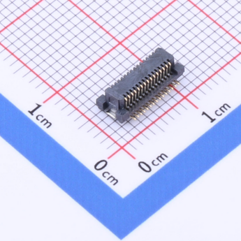
Extreme Pitch: 0.4mm or 0.5mm; 50–200 pins; typically with LCP housing (resistant to 260℃ soldering heat) and gold-plated pins (withstand >100 insertions).
Technical Demands: Alignment precision ±0.05mm (requires SMT machines); data rates up to 10Gbps (e.g., PCIe 4.0).
Applications: Smartphone mainboards and display modules (e.g., iPhone's 0.4mm connectors), VR headsets for high-speed data links.
Mated Height: 1.5–3.0mm using short pins (1.0–1.8mm) and thin plastic bases (0.3–0.5mm thick).
Applications: Tablets (thickness <7mm), smart card readers with limited internal space.
Common Height: 5mm; balances contact reliability (adequate pin length) and space use. Covers 80% of consumer and industrial electronics.
Height Range: 10–30mm; uses extended pins (5–20mm) to connect distant PCBs, e.g., server mainboard to daughter cards.
No shielding; used for GPIO, power signals.
Examples: Header & socket for appliance control boards, transmitting button signals.
Differential pair layout with impedance 90Ω ±10%; pitch <0.8mm.
Applications: USB 3.0, HDMI between TV motherboard and interface boards.
With metal shielding (to block EMI), 50Ω impedance.
Applications: Bluetooth/WiFi module to motherboard (e.g., 2.4G/5G connections in routers).
Single Row: 2–20 pins; for simple signals (e.g., sensors to mainboard); saves horizontal space.
Dual Row: 4–100 pins; denser than single-row (saves ~50% board space); standard in phones (e.g., battery connectors).
Multi-Row (≥3 rows): >100 pins; for complex systems (e.g., industrial PCs with multiple power/signal lines); requires ultra-precise soldering (tolerance ≤0.03mm).
Space Constraints:
Determine PCB stack height and available area. For ultra-thin devices, use ≤3mm low-profile connectors; for industrial use, 5–10mm is acceptable.
Signal Requirements:
Low-speed (e.g., button signals): header & socket.
High-speed (e.g., USB 3.1): <0.8mm differential connector.
High-frequency: use shielded RF connectors.
Environmental Conditions:
Vibration-prone: floating connectors (e.g., cars, robots).
High temperatures (>85℃): LCP materials (resist up to 125℃).
Humid/outdoor: IP67 waterproof models.
Cost Consideration:
For mass production: choose standard models (e.g., 2.54mm headers for low unit cost).
For precision equipment (e.g., medical instruments): go for reliable brands (e.g., TE, Molex) with >1000 mating cycles.
Board-to-board connectors must be matched to the application.
Consumer electronics demand small pitch (0.4–0.8mm) and low height.
Industrial equipment values vibration resistance (floating type) and high current capacity.
High-frequency/high-speed scenarios require shielded designs.
Tip: One device may use multiple connector types—e.g., 0.5mm high-speed connectors for mainboard, 2.54mm headers for sub-board. The key is balancing performance, space, and cost.
Need help with model recommendations?
Provide your stacking height, signal rate, and operating temperature, and get a tailored selection list with pitch, pin count, and brand suggestions.


Copyright © Shenzhen Kinghelm Electronics Co., Ltd. all rights reservedYue ICP Bei No. 17113853
