Service hotline
+86 0755-23615795

Release date:2025-08-05Author source:KinghelmViews:200
Bluetooth chip antennas are widely used in compact devices such as smartwatches and Bluetooth earphones due to their small size and easy integration. However, around 30% of signal issues stem from improper handling—metal obstruction during installation may reduce the transmission range from 10 meters to just 3 meters, or impedance mismatch can lead to frequent disconnections. This article breaks down the complete usage process of Bluetooth chip antennas, covering pre-installation preparation, core operation standards, performance debugging, and maintenance tips to help you avoid common pitfalls and ensure signal stability.
Proper antenna-device matching is critical for optimal performance:
Frequency Matching: Ensure the antenna supports the "2.4GHz ISM band" (2.4–2.485 GHz). Avoid mistakenly using 5GHz Wi-Fi antennas, which cannot receive Bluetooth signals.
Impedance Matching: Check the antenna's datasheet to confirm a 50Ω impedance (tolerance ≤5Ω), which should match the RF port impedance of Bluetooth modules (e.g., CC2540, nRF52832).
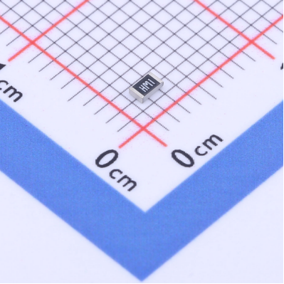
Size Compatibility: Select the antenna size based on device space (e.g., 10×10 mm for earphones, 20×20 mm for smart gateways). Reserve at least a 3 mm metal-free zone around the antenna to prevent signal blockage.
Essential Tools:
Constant temperature soldering iron (300–350℃ to avoid pad damage)
Flux (removes oxidation for <0.1Ω contact resistance)
Multimeter (check for shorts after soldering: red probe on feed point, black on ground; should be open circuit)
Anti-static wrist strap (especially in dry environments to prevent ESD damage)
Environment Requirements:
Avoid metal workbenches (use wood boards as insulation)
Stay clear of strong electromagnetic interference (e.g., near welding machines) to prevent tuning errors
Clean the PCB antenna area with alcohol swabs to remove oil and oxidation (prevents cold solder joints)
If metal components (e.g., batteries, shields) are nearby, ensure ≥5 mm clearance to avoid 10–15 dB signal attenuation
Mark the grounding area: ensure proper path between antenna ground pads and PCB ground layer via copper traces or vias (resistance <0.05Ω)
Antenna radiation depends on installation direction:
Omnidirectional chip antennas (e.g., rectangular): should be placed horizontally (parallel to ground), ensuring even 360° radiation. Misalignment >15° may cause 8dB signal loss in one direction.
Directional chip antennas (e.g., with bent structures): aim the radiating surface (usually the patterned side) toward the target direction (e.g., earphone antenna faces smartphone)
Refer to the antenna datasheet's radiation pattern and mark the "optimal radiation direction" before fixing.
Critical for efficient signal transmission:
Feed Point: Apply a small amount of solder (0.3 mm wire), quickly solder the center feed pad to the RF interface. Solder time ≤2 seconds to avoid substrate damage.
Ground Pads: At least two ground pads on the antenna edges must connect to the PCB ground layer. Ensure <0.1Ω resistance (test with multimeter).
Don'ts: Avoid excess solder (can cause shorts), or pressing down too hard (may crack ceramic substrate).
Some antennas use conductive adhesive (e.g., FPC flexible antennas):
Clean dust, apply a thin glue layer (≤0.1 mm), press for 10 seconds for bonding
Let it cure for 24 hours before powering on (to avoid intermittent contact)
For vibration-prone devices (e.g., in vehicles), reinforce with hot glue on antenna edges to prevent long-term resistance increase
For antennas with external feed cables (e.g., IPEX connectors):
Align the IPEX male plug with the board connector, gently press until you hear a “click” (ensures secure connection)
Route the cable carefully, avoid sharp bends (bend radius ≥5× cable diameter; for 1 mm diameter, radius ≥5 mm). Each bend may cause ~0.5 dB loss.
For humid environments (e.g., bathroom devices), use waterproof glue over solder joints and connectors (prevents oxidation)
Do not cover the antenna with metal coatings or conductive paint (blocks signals)
In small devices (e.g., fitness bands), keep a 0.5 mm air gap above the antenna (no parts above) to boost efficiency by ~10%
Use the multimeter in continuity mode:
Feed point ↔ RF port: should be conductive (buzzer sounds)
Feed point ↔ ground: should be open (no buzzer)
For external feed antennas: check resistance at both cable ends (<1Ω)
Use Bluetooth test tools (e.g., nRF Connect App) to measure RSSI at 1 meter:
Excellent: -40 to -60 dBm
Good: -60 to -75 dBm
Poor: < -80 dBm (indicates issues)
At 10 meters, RSSI drop should be ≤20 dB (e.g., -50 dBm at 1 m → ≥ -70 dBm at 10 m). Higher loss may suggest obstruction or poor soldering.
Transmit data continuously (e.g., 100 bytes/sec) for 30 minutes; record packet loss:
Acceptable Loss: ≤1%
Problematic: >5%, check:
Impedance mismatch: Use a network analyzer; VSWR should be ≤1.5
Poor grounding: Re-solder ground pads, ensure ground resistance <0.05Ω
Avoid Strong Vibrations: Soldered antennas may detach under vibration. Check solder joints every 6 months for industrial use.
Prevent Temperature Shocks: Ceramic chip antennas work best from -40 to 85°C. Avoid placing near heat sources (e.g., CPU heat sinks). At >100°C, dielectric constant changes can shift signal frequency.
Cleaning Precautions: Wipe with a dry cloth only. Avoid alcohol or solvents that may corrode the substrate or conductive layers.
No Modifications: Do not cut or bend the antenna, which will break impedance matching. VSWR may jump to >3.0, causing complete signal failure.
The key to effective Bluetooth chip antenna usage is precise matching and standardized handling. Confirm frequency and impedance before installation, control temperature and duration during soldering, and focus on RSSI and packet loss during tuning. Most signal issues stem not from the antenna itself but from metal obstructions, poor soldering, or incorrect orientation. Following the above steps can unleash over 90% of the antenna’s potential, ensuring stable communication within a 10–15 meter range.
If signal issues persist after debugging, feel free to share your antenna model and device layout for a customized installation optimization plan (e.g., adjusting ground area or avoiding nearby metal parts).


Copyright © Shenzhen Kinghelm Electronics Co., Ltd. all rights reservedYue ICP Bei No. 17113853
