Service hotline
+86 0755-83975897

Release date:2021-12-28Author source:KinghelmViews:845
With the change of war demand and the progress of science and technology, the "gold content" of air combat is becoming higher and higher. The development of fighter airborne radar is a typical example. In terms of appearance, the most intuitive part of the "evolution" of radar equipment is the change of antenna. The following is a brief talk about the development of airborne radar antenna.
Airborne radar evolved from the simple air search and ranging function in the early stage to now, it should not only take into account the search, tracking and fire control guidance in a large area, but also realize multi-function such as ground mapping and SAR imaging. Generally speaking, airborne radar requires the antenna to have the characteristics of high gain (easy to increase the detection distance), narrow beam (easy to increase the angle measurement accuracy), low sidelobe (anti-jamming), etc. And achieve high gain and narrow beam. The simplest is to use directional antennas, such as Yagi antenna and paraboloid (single reflector) antenna. The size of Yagi antenna is too large, and compared with Yagi antenna, paraboloid antenna is easier to achieve low sidelobe. Therefore, paraboloid antenna is widely used in airborne radar in the early post Cold War period.
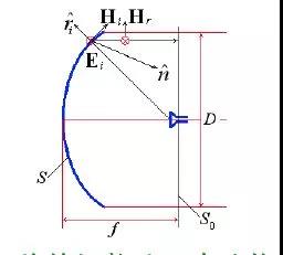
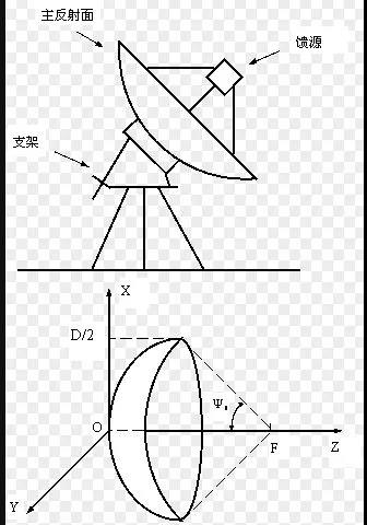
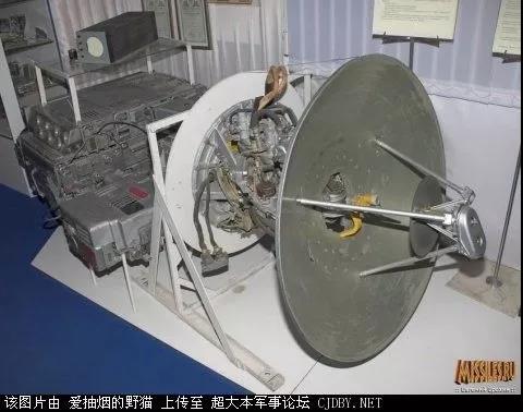
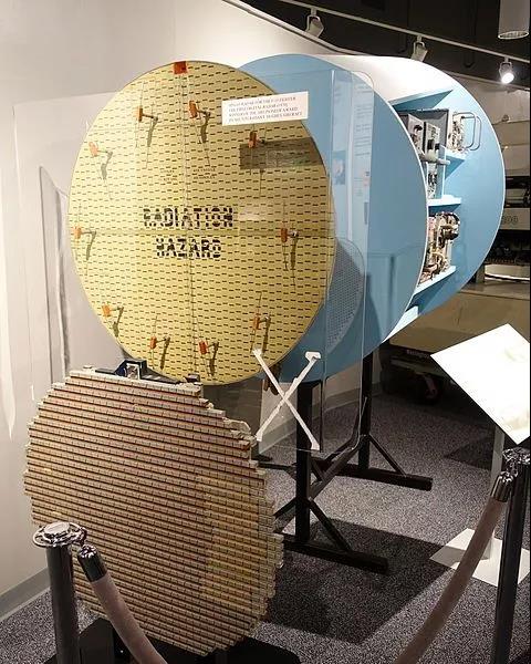
Parabolic antenna (single reflector antenna).This kind of antenna uses a paraboloid with large size as the main surface, and a horn at the center in front of the main surface as the feed (positive feed), (the horn can also deviate from the center, which is called bias feed). Its working principle is quite similar to the paraboloid mirror in optics. The working principle is that when the antenna works in the radiation mode, the spherical wave radiated by the horn hits the paraboloid, which transforms the spherical wave incident by the horn into a plane wave and radiates it into free space. In the working and receiving mode, the main reflecting surface converges the plane wave transmitted from the free space, which is called spherical wave, and makes it "return" to the feed horn. This type of antenna is not difficult to process in X-band and below, has simple structure and low cost. However, the disadvantages are also obvious. Generally, the paraboloid antenna is easy to achieve high performance when the focal diameter ratio (the ratio of the distance from the horn to the reflecting surface to the size of the main reflecting surface) is high, so the overall section of the antenna is high and the volume is large. Especially when the antenna rotates and scans as a whole, it will greatly occupy the head space, so its scanning angle is also limited. In order to solve these difficulties, a double reflector called "Cassegrain" came into being.
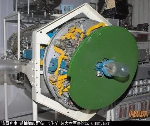
Cassegrain antenna.It is an improved antenna in the form of single reflector antenna. Compared with the single reflector antenna, the additional sub reflector can preliminarily optimize the electromagnetic wave emitted by the horn and make it present a more ideal distribution, which is reflected back to the main reflector, which then turns the shaped spherical wave into a plane wave and radiates it into the free space. The advantage is that it can improve the antenna aperture efficiency, improve the gain, greatly reduce the focal diameter ratio, reduce the overall profile of the antenna and reduce the volume. After the receiver and feeder become the main plane, it is more conducive to the routing arrangement of the system and reduce the system noise. However, the introduction of the secondary reflector will also lead to the problem of increasing the shielding of the main surface, which will in turn reduce the overall gain of the antenna and raise the sidelobe level.
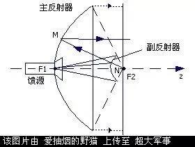
Basic composition and working principle of Cassegrain antenna
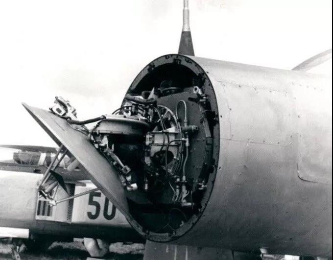
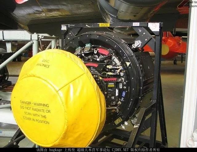
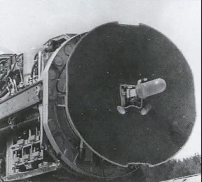
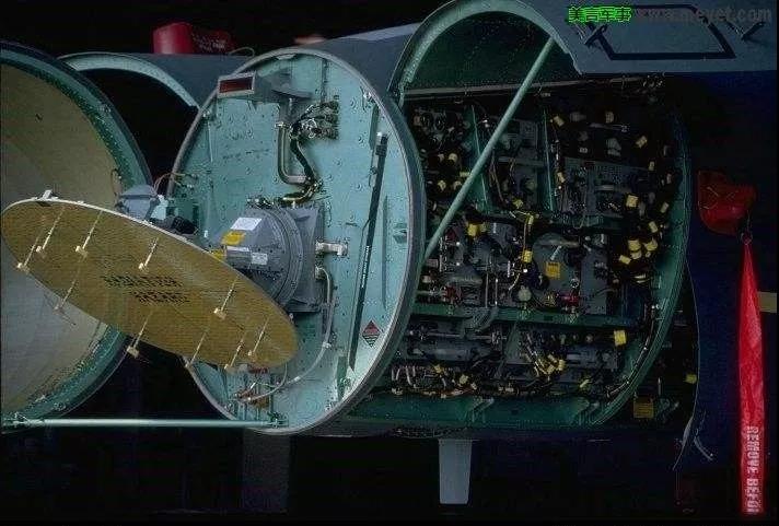
In order to solve the problem of sub reflector occlusion, an antenna called inverted Cassegrain is proposed and widely used in airborne radar. Inverted Cassegrain, also known as deformed Cassegrain antenna. Based on the Cassegrain antenna, the position of the sub reflector is changed into a polarization grid paraboloid, and the position of the main reflector is changed into a polarization torsion plate. (in fact, in the inverted card antenna, the positions of the main and auxiliary planes are obviously different from those of ordinary Cassegrain.) The working principle is quite different from that of Cassegrain antenna: the horn feed at the polarization torsion plate almost completely reflects the horizontal linear polarization electromagnetic wave sent out by the front polarization grid, changes the spherical wave into a plane wave, hits the rear polarization torsion plate, turns the horizontal polarization wave into a vertical linear polarization electromagnetic wave, and transmits it from the front polarization grid, Radiate into free space. In short, although the beam emitted by the inverted card feed is also reflected twice, it is different from the ordinary Cassegrain antenna. There is a polarization torsion process in the middle. The polarization grid in front of the antenna only blocks the horizontal polarization electromagnetic wave and has little effect on the vertical linear polarization wave. Incidentally, in order to combat ground clutter, airborne radar antennas are mostly vertical linear polarization antennas. It realizes beam scanning by properly rotating the polarization torsion plate. Therefore, the inverted card antenna solves the problem of shielding the sub reflector, and can slightly offset the feed and polarization grid, further reducing the profile of the overall antenna. Because of its unique advantages, inverted card antenna is very popular in the second generation machine.
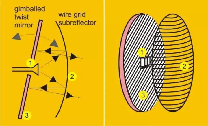
Working principle of inverted card antenna: polarization grid is at the front cross bar. The polarized torsion plate is arranged at an inclination of 45 degrees at the back

The basic working principle of the above antennas is based on the form of reflector, which is nothing more than single reflector or double reflector, polarization torsion and other details. By controlling the distance between the horn and the main surface, adjusting the irradiation taper and so on, it is easy to achieve high gain and low sidelobe. Satisfactory performance can also be achieved in the early stage. Nevertheless, although the processing requirements of the antenna working in the form of reflector are not high (the X-band is good, and the difficulty increases sharply in the higher frequency band), the cost is acceptable. However, with the improvement of airborne radar performance, new requirements are put forward for the antenna, such as larger scanning angle, lower sidelobe and shaped beam. The inherent defects of the inverted card antenna include that there will always be energy leakage (which will reduce the aperture efficiency and lose the gain), the beam distortion during scanning is also serious (the main lobe gain decreases, the main beam becomes wider and the side lobe rises), and there is always the problem of large antenna weight. Therefore, we all think that the three generations of aircraft that want to seize the air control: mig29 and Su 27 used inverted Cassegrain antennas in their early days, which is somewhat shabby.
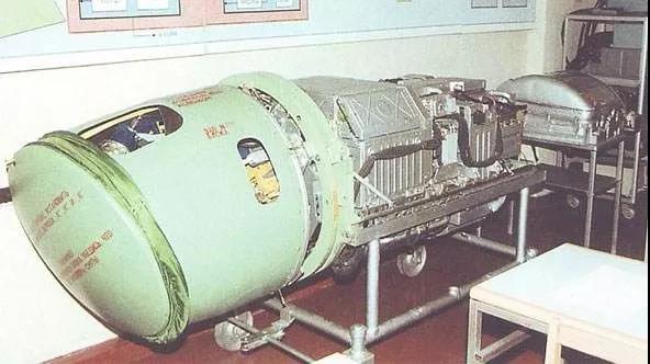
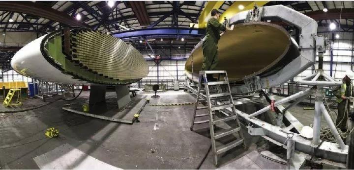
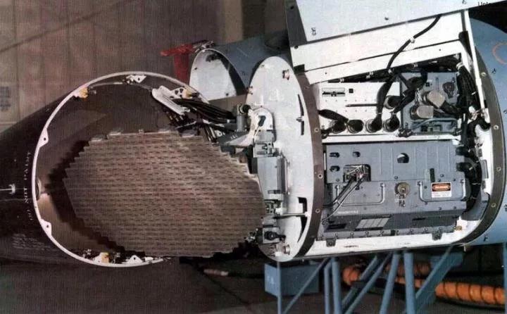
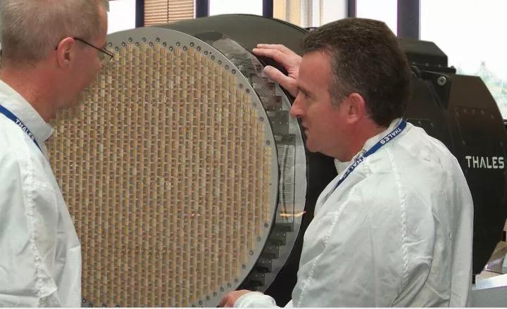
We know that in order to meet the requirements of high gain, narrow beam and low sidelobe of airborne radar, paraboloid antenna has been used earlier because of its simple structure. There is also a slightly more complex antenna with better performance, that is, planar array antenna. Planar array antenna is a typical array antenna. From tens to hundreds, even thousands of small unit antennas are evenly arranged on the array surface according to certain rules and spacing. A single unit antenna may have a wide beam and low gain, but relying on many unit antennas on the antenna array and working together, it can achieve a high gain, narrow beam and even ultra-low sidelobe (it can even be upgraded to a planar phased array in the later stage). Therefore, due to its excellent performance, planar array antenna quickly replaced reflector antenna and became the mainstream of various third-generation, third-generation modified and fourth-generation airborne radar systems. At present, the advanced airborne radar - phased array radar is almost in the form of plane array antenna.
Common planar array antennas include waveguide (flat plate) slot array, open waveguide array, dipole array, Vivaldi antenna array, microstrip patch antenna array and so on.
Waveguide slot array is a common microwave transmission structure. The waveguide surface is slotted (grooved), so that the small slot becomes an antenna to radiate electromagnetic waves. It has the advantage of matching with the feed structure and large power capacity. Airborne waveguide slot looks like it is opened on a flat plate, so it is sometimes called flat plate slot array.
Similarly, there is an open waveguide array antenna. The open waveguide also uses the waveguide structure, but it is not slotted, but directly uses the waveguide port surface to radiate electromagnetic waves. Because the profile of this open waveguide form is slightly larger and the weight is too heavy, it is more common in land-based or shipborne radars, and this form is rarely used in airborne radars.
The above structure using waveguide for feeding and radiation is conducive to antenna matching. Large power capacity is its remarkable advantage. However, the antenna bandwidth is often limited and the weight is difficult to control. Subsequently, many novel designs are gradually used in airborne radar system.
In fact, in the late cold war, in order to make the airborne radar obtain faster scanning speed and more powerful performance (such as simultaneous search and tracking, fire control guidance and ground detection), engineers used phased array antenna for the airborne radar, which is still regarded as an advanced technology. The appearance of phased array antenna is not much different from that of common planar array antenna. It can even be simply understood as modifying the feed structure based on ordinary machine scanned planar array antenna (of course, the back-end transmitter / receiver and signal processing algorithm will change greatly). A passive phased array antenna (PESA) can be obtained by adding a phase shifter to the rear end of the antenna unit. If you don't like adding a tr component to the phase shifter, you can get an active phased array antenna (AESA). For antenna engineers, the same antenna array can be used as AESA or PESA. Therefore, for planar array antenna, it has great potential to be upgraded into phased array antenna.
For the radar upgraded to AESA antenna, it has greater transmission power, longer detection distance, more sensitive beam scanning and more powerful beam shaping function. It is also easier to obtain an average sidelobe of - 50 and - 60dB.
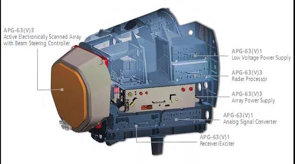
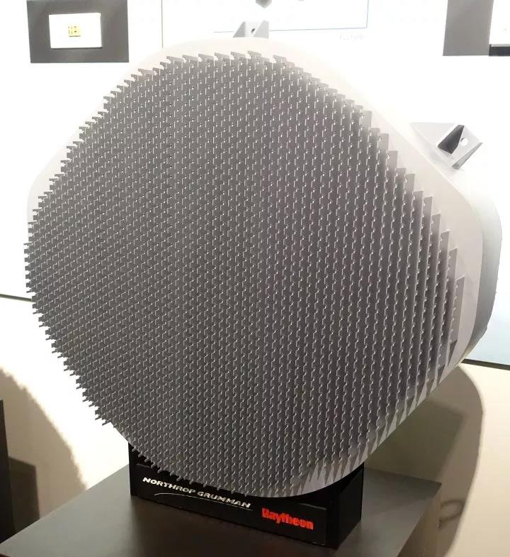
The front protruding part is easily mistaken for the TR component. Strictly speaking, it is actually the antenna surface. The TR component is connected to the rear of the antenna (although the TR component is generally processed into one with the antenna, it is still distinguished here)
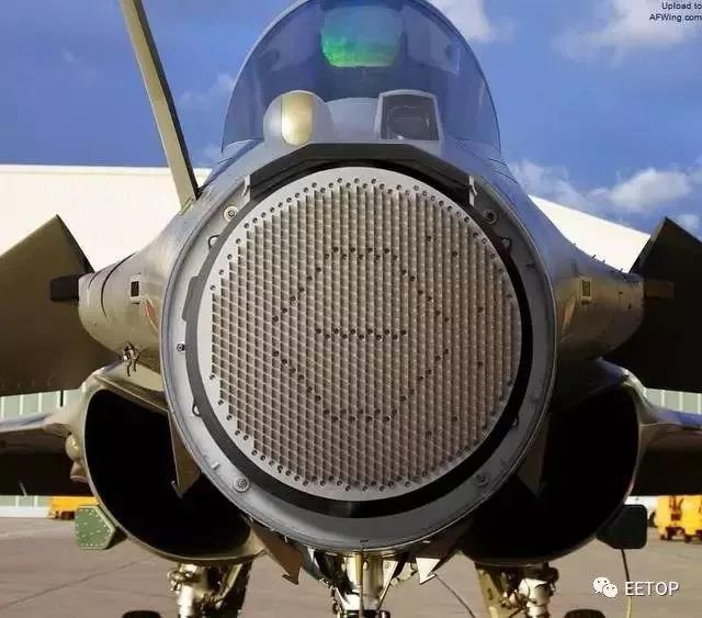
The rbe2 AESA radar used in the new gust (as shown in the figure below) adopts Vivaldi antenna array. The characteristic of this antenna unit is that the bandwidth is very wide, so the bandwidth of the whole antenna array can be expanded.
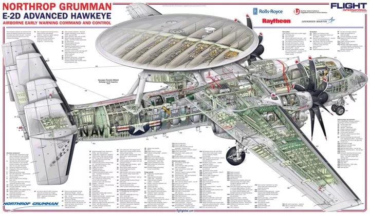
Of course, there are some special ones. For example, the following apy9 radar used by E2d early warning aircraft with Yagi antenna as unit. Compared with the UHF band electromagnetic wave length, its antenna size is very limited. In order to obtain a more ideal narrow beam and high gain, its antenna unit beam must be narrowed. Therefore, Yagi antenna has become an ideal choice. The high gain Yagi antenna as a unit can significantly improve the gain of the array. But things are always relative. The narrow unit beam of Yagi antenna greatly limits the wide-angle scanning ability of the array. When the antenna scanning angle deviates greatly from the normal, the decrease of gain and waveform distortion will be very obvious. Therefore, apy9 uses the combination of electromechanical scanning to make up for the deficiency.
It is the development of phased array technology that makes the airborne antenna enter a new stage.
The development of antenna is an epitome of the overall technical development of radar. Although we can not determine the radar performance according to the appearance of the antenna and measure the overall performance of the radar, we often pay attention to the coordination and balance between systems in engineering. If the overall performance of a radar system is advanced, the antenna can not be worse. In the future, engineers will continue to overcome problems such as large angle scanning of phased array antenna (expanding the scanning range of & plusmn; 60 degrees at this stage), UWB, common aperture, conformal and so on, so as to promote the development of airborne radar system.
This article comes from the "network". Please contact us to delete it if you have any infringement problemsSupport the protection of intellectual property rights. Please indicate the original source and author for reprint.


Copyright © Shenzhen Kinghelm Electronics Co., Ltd. all rights reservedYue ICP Bei No. 17113853
