Service hotline
+86 0755-83975897

Release date:2024-03-12Author source:KinghelmViews:147
4.Product Detail
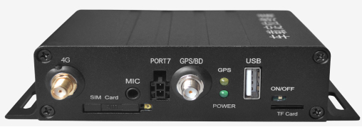
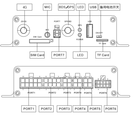
4.1 Product Appearance Image
The following image shows a schematic diagram of the front side of the vehicle positioning terminal.
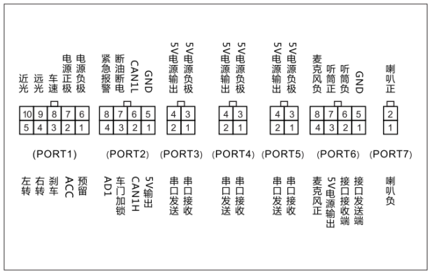
4.2 Wiring Harness Definition
4.3 Function Introduction
4.3.1 Positioning Monitoring Function
The terminal provides real-time information on time, longitude, latitude, speed, altitude, and direction of the positioning status, which can be stored internally in the terminal and uploaded to the monitoring platform via wireless communication.
The terminal can receive one or more positioning requests from monitoring platforms for uploading positioning information and can stop real-time reporting to the corresponding center as required by the monitoring platform.
The terminal can store not less than 10000 positioning information entries in a first in, first out manner during communication interruption (blind zone) and transmit the stored positioning information upon communication restoration, with the option to upload using compression if needed.
The terminal supports time, distance interval, or external time-triggered uploading of positioning information. Even when the terminal is in sleep mode, it can upload positioning information at certain time intervals, with the intervals set by the monitoring platform.
The terminal can automatically upload positioning data for alarm vehicles or key vehicles according to the positioning method and time interval set by the monitoring platform.
Status information (longitude, latitude, detailed address (optional), positioning time, terminal ID, number of satellites, signal strength) can be retrieved via SMS.
A. Scheduled Monitoring
The terminal uploads coordinate data to the monitoring platform at set time intervals, with a minimum upload interval of 5 seconds.
B. Distance-based Monitoring
The terminal uploads coordinate data to the monitoring platform at set distance intervals, with a minimum upload interval of 50 meters.
C. Turn Point Data Re-transmission
The terminal uploads location messages to the monitoring platform when the vehicle turns, with a continuous change in vehicle angle exceeding 15 degrees for 3 seconds.
4.3.2 Wireless Communication Function
A. GPRS Communication Mode
Supports GPRS as a communication method with a modular design for wireless communication functions.
B. Blind Zone Data Reporting
When a vehicle enters a GSM signal blind zone, it automatically stores positioning data and uploads location information to the center once the mobile signal is restored, with the capability to cache at least 10000 location report messages.
C. Primary and Backup Server Switching
If the terminal fails to connect to the primary server three times consecutively, it switches to the backup server; if the backup server connection fails three times consecutively, it switches back to the primary server.
4.3.3 Alarm Notification Function
When triggered, the terminal should immediately upload alarm information to the monitoring center or send alarm messages to designated phones as needed. It can also receive instructions from the monitoring center to cancel alarms, with the alarm phone numbers set remotely by the monitoring center. When the monitoring center needs to send instructions to the terminal based on the vehicle's uploaded position or status information for safety supervision, the terminal should audibly alert the driver with voice prompts.
A. Manual Emergency Alarm
Drivers trigger manual alarms based on on-site emergencies like robbery, traffic accidents, or vehicle malfunctions by pressing the emergency alarm button to upload alarm information to the monitoring center while deactivating the voice alert module.
B. Overspeed Reminder
a) When the terminal has valid positioning and the speed exceeds the maximum allowed speed for at least 3 seconds (user-configurable), it triggers an overspeed alarm.
b) Overspeed alarms cannot be cleared from the monitoring platform; the alarm stops automatically when the terminal speed falls below the allowed maximum.
c) In case of invalid positioning, the overspeed alarm stops automatically.
C. Fatigue Driving Reminder
The intelligent onboard terminal automatically reports fatigue driving alarms to the monitoring platform when the driver exceeds the designated continuous driving time.
D. Insufficient Cumulative Driving Time Reminder
If the total driving time of the vehicle for the day does not meet the terminal's specified daily driving time, the terminal sends a reminder to the monitoring platform.
E. Overtime Parking Alarm
If the vehicle parks for longer than the specified time during the journey, the intelligent onboard terminal automatically reports an alarm to the monitoring platform.
F. Area (Geofence) Alert
When the vehicle enters/exits user-prohibited areas, the intelligent onboard terminal automatically reports alarms to the monitoring platform. The platform can send messages to set circular areas, rectangular areas, polygonal areas, or routes for the terminal, which then determines if alarm conditions are met based on area and route properties, including overspeed alarms, entry/exit alarms, and insufficient/excessive driving time alarms. The location report message includes corresponding location additional information.
The platform can also send messages to delete circular areas, rectangular areas, polygonal areas, or routes stored in the terminal.
Setting/deleting area and route messages require the terminal to respond with a general acknowledgment message.
The monitoring platform can send geofence information to the terminal containing:
Ø Time: Multiple selection of weekdays, time periods;
Ø Shape: Polygon, rectangle, circle;
Ø Type: Entry reminder, boundary crossing reminder, entry-exit reminder.
G. Fault Alert for Positioning Module
When the positioning module encounters a fault, the terminal sends an alert message.
H. Reminder for Unconnected or Cut-off Positioning Antenna
The intelligent onboard terminal can monitor the status of the positioning module's antenna. If the positioning antenna experiences a short circuit or is cut, the terminal sends a positioning antenna alarm signal to the monitoring platform. In the absence of a confirmation command from the monitoring platform, the terminal must send positioning antenna fault alarms to the monitoring platform at 5-second intervals. Once the antenna is functioning normally, the positioning antenna fault alarm message is automatically canceled.
I. Low Fuel Reminder
If the vehicle is equipped with a fuel sensor or fuel conversion box and the fuel level drops below a specific value, the terminal sends a reminder message to the monitoring platform.
J. Vehicle Light Status Reminder
The terminal device retrieves information on the vehicle's indicator lights and reports it to the monitoring platform.
K. Voice Reminder
After the vehicle enters any of the above alert states, it provides different voice reminders, such as for a fuel theft alarm, saying "Fuel level has dropped abnormally, please check the fuel tank status."
4.3.4 Vehicle braking function
The vehicle braking function means cutting off the fuel and power supply to the vehicle, preventing the vehicle from starting to achieve the braking purpose. The authorized party sends the cut-off fuel and power command through the vehicle monitoring platform or GSM SMS platform, and the terminal receives the command to activate the anti-theft system relay to cut off the ignition circuit or fuel line.
If the braking function is not effective during driving, the fuel and power should be cut off after the vehicle stops.
4.3.5 Call and voice function
A. Call monitoring
It can achieve call monitoring under specific conditions (such as alarm status) based on parameter settings.
The terminal has two monitoring modes: active monitoring and passive monitoring. During the process of answering or dialing a monitoring call, the voice is switched to one-way, meaning the monitoring center can hear the conversation in the vehicle, but the vehicle occupants cannot hear the center. Once the center hangs up, the monitoring is completed.
During monitoring, the speaker is turned off. The monitoring meets the following technical requirements:
Ø The monitoring platform sends a monitoring command, and the terminal dials the monitoring number provided in the command to enter the monitoring state;
Ø When dialing the monitoring number, if not connected on the first attempt, it can be redialed three times consecutively with a 30-second interval each time
B. Remote call
Operate the relevant keys to initiate a call to the designated phone number of the monitoring command center or dispatch service center.
The terminal may have circuit domain call function and call management function, including call restrictions, phone book management, call back, and automatic answer for incoming calls. The terminal phone book should have a storage capacity of no less than 20 contacts.
C. Sleep mode
The terminal should have a vehicle ACC ignition detection function. After the vehicle is turned off, the terminal sends a signal to the monitoring center indicating the vehicle is turned off and automatically enters sleep mode. The terminal in sleep mode should meet the following technical requirements:
- Turn off all unnecessary devices except the wireless communication module, and the satellite positioning module automatically wakes up when data needs to be uploaded;
- The data upload frequency can be remotely set by the monitoring center or automatically reduced based on the parameters set during initialization;
- The terminal should switch to the built-in backup battery for power supply after low battery voltage alarm, and automatically shut down when the built-in backup battery is depleted;
- During sleep mode, the average power consumption of the terminal should not exceed 2 watts.
4.3.6 Message function
A. Text message sending
The platform sends text messages to notify the driver in a specified manner. The terminal replies with a general acknowledgment message.
B. Event reporting
The platform sends event setting messages to the terminal, which stores the event list. The driver can select from the event list when encountering corresponding events and send an event report message to the platform. The event setting message requires a reply from the terminal with a general acknowledgment message. The event report message requires a reply from the platform with a general acknowledgment message.
C. Inquiries
The platform sends inquiry messages to the terminal, containing questions with candidate answers. The terminal immediately displays the questions for the driver to select, and then sends an answer message to the monitoring platform. The inquiry message requires a reply from the terminal with a general acknowledgment message.
D. Information on demand
The platform sends information on demand menu setting messages to the terminal, containing a list of information services. The driver can select to subscribe/cancel specific information services through the menu, and the terminal sends an information subscription/cancellation message to the platform.
Once an information service is subscribed, the terminal will periodically receive information service messages from the platform, such as news or weather forecasts. The information on demand menu setting message requires a reply from the terminal with a general acknowledgment message. The information subscription/cancellation message requires a reply from the platform with a general acknowledgment message. The information service message requires a reply from the terminal with a general acknowledgment message.
4.3.7 Driving recorder function
A. Self-check function
After the device is powered on, it will conduct self-checks on various components and interfaces of the system. Upon passing the self-check, it will emit a beep sound and display through system indicator lights.
B. Real-time time, date, and driving time recording, storage, and collection function
The recorder can provide Beijing time, date, and clock, recording the real-time date in the format of year, month, day, and the real-time clock in the format of hour, minute, second.
C. Driving management function
a) Daily statistics
Capable of calculating the daily driving distance, driving time, and cumulative driving distance for each day.
b) Minute-by-minute speed recording
Can record the driving status information within the last 360 hours, providing the average driving speed value for each minute corresponding to the real-time clock during the vehicle's journey.
c) Vehicle driving data statistics
The comparison recorder software can statistically compare driving data by vehicle and driver, allowing administrators to better understand the operation status of the vehicles and drivers under their jurisdiction over a certain period.
D. Accident prevention function
a) Overspeed alarm
When the vehicle speed exceeds a preset overspeed value (adjustable, e.g., 120 km/h), the recorder will immediately emit a "beep, beep..." alarm sound to remind the driver to slow down and prevent accidents.
b) Overspeed record
When the vehicle speed exceeds the overspeed value, the speed curve can analyze the number of overspeed instances, start time of overspeed, duration, maximum speed, and driver code.
c) Fatigue driving alarm and recording function
When the same driver drives continuously for nearly four hours (according to national standards, driving continuously for more than four hours is considered fatigue driving, and insufficient rest of less than 20 minutes during the journey is considered continuous driving), the recorder will audibly remind and start recording after exceeding four hours.
E. Suspicious point record analysis function
The recorder records routine data in the last twenty seconds before parking, with a 0.2-second interval recording of the vehicle's speed, braking, and other information.
F. Display and print function (external)
Can display through a handle and real-time print the average vehicle speed record per minute within the last fifteen minutes, overtime driving (fatigue driving) record, and relevant information of the vehicle and driver.
G. Vehicle information and driver profile management function
The recorder has the function of recording driver identity. Before each drive, the driver inserts a USB identity card to confirm their code.
Using the recorder software, vehicle management files and driver safety records can be established. The management software provides a user-friendly interface for entering, modifying, querying, statistical analysis, and printing reports of vehicle information and driver profiles. Administrators can intuitively view driving curves, overspeed records, suspicious point data, fatigue driving records, driving distance, and other information.
H. Power-off protection
The recorder has power-off protection function, ensuring data is not lost within ten years.
I. Data communication function
Can collect recorder data and set parameters through standard USB interface, serial port, or optional wireless module.
4.3.8 Other functions
A. Phone book setting
The monitoring platform sends a message to set the phone book on the terminal, which requires a reply from the terminal with a general acknowledgment message.
B. Remote upgrade
Through the monitoring platform or server software, send terminal software upgrade packages to the terminal for remote software version upgrades.
4.4 Operation Instructions
This device provides four communication methods: USB communication, RS232 interface communication, SMS communication, and GPRS communication.
a) USB Communication
First, format the USB flash drive with FAT or FAT32 format. Connect the USB flash drive to the USB interface of the vehicle-mounted wireless terminal. The terminal will automatically enter the USB communication interface when it detects a USB device connected. After the communication is completed, return to the clock mode.
Note: If there are no collected files in the USB flash drive, the collected data will be based on the national standard. If there are collected files, the data collected will include national standard data and trajectory data. Do not unplug the USB flash drive during the communication process, as it may damage the device.
b) GPRS Communication
Using GPRS communication, it is possible to send and receive settings such as maximum speed, suspicious point data, and text messages in the dispatch monitoring center.
c) Setting Vehicle Information and Parameters
Vehicle information and parameters can be remotely set through USB, SMS, and GPRS: license plate number, characteristic coefficient, overspeed alarm value, vehicle VIN, speed mode selection (car pulse speed mode, satellite positioning speed mode, and CAN speed mode), IP address and port, UDP port, and SIM card number. Automatic calibration of the characteristic coefficient is also available.
d) Automatic Calibration of Characteristic Coefficient
When parking, insert the setting card into the USB flash drive and select the characteristic coefficient calibration interface using the "Menu" key and "Scroll Down" key. Follow the instructions for operation. This operation can automatically change the characteristic coefficient in the device and calibrate the speed recorded by the satellite positioning car driving recorder with the speed displayed on the car dashboard.
e) Data Collection
Connect the prepared collection card to the vehicle-mounted wireless terminal. The LCD on the handle will display "Collecting data... Please wait!" After successful collection, there will be two beeps as a prompt. After the backlight goes off, remove the USB flash drive to view the collected 32KB national standard data and trajectory data.
f) Manual Speed Calibration
New characteristic coefficient = Current characteristic coefficient * Speed displayed on the satellite positioning car driving recorder / Speed displayed on the car dashboard
Note: The calculation is most accurate when the car dashboard displays 60Km/h. Then, use the setting card on the USB flash drive to change the characteristic coefficient in the main unit based on the calculated value.


.jpg)
.jpg)
.jpg)
.jpg)
Copyright © Shenzhen Kinghelm Electronics Co., Ltd. all rights reservedYue ICP Bei No. 17113853
