Service Hotline
Tech Applications

Tech Applications

How to Choose the Right Coin Cell Battery Holder: A Guide to CR2032, CR1220 and CR2450
2026-11-04
230
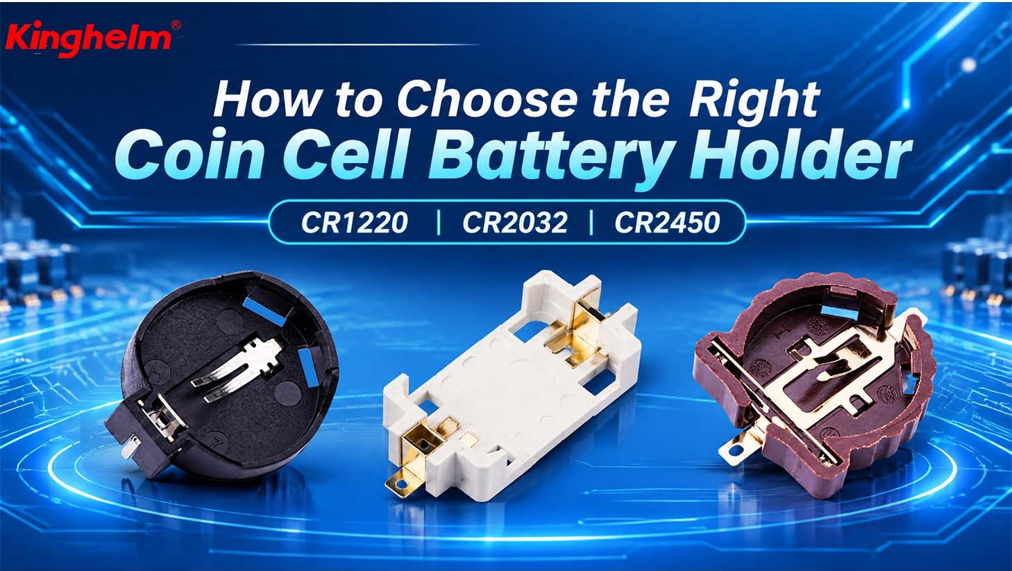
Choosing a coin cell battery holder starts with the battery model, but it does not end there. A CR2032 cell has a nominal diameter of 20.0 mm and a nominal thickness of 3.2 mm, yet its holder also has to fit a PCB, withstand the assembly process and allow battery replacement. A holder can match the cell and still be wrong for the board.
Even two holders designed for the same battery size may differ in contact arrangement, retention method, external dimensions and mounting style. This guide looks at three common coin cell sizes - CR1220, CR2032 and CR2450 - and explains what to consider when comparing holder structures and checking PCB compatibility. It also introduces selected Kinghelm battery holder models to show how these factors apply to actual product choices.
Coin Cell Battery Sizes: CR1220, CR2032 and CR2450
The first step is to identify the exact battery model. CR1220, CR2032 and CR2450 are all lithium manganese dioxide coin cells, and their model names refer to nominal dimensions rather than the dimensions of a holder. The first three digits indicate nominal diameter, while the final two digits indicate nominal thickness.
| Cell model | Nominal diameter | Nominal thickness |
|---|---|---|
| CR1220 | 12.5 mm | 2.0 mm |
| CR2032 | 20.0 mm | 3.2 mm |
| CR2450 | 24.5 mm | 5.0 mm |
These values describe the cells, not the holders. A holder's outer envelope is usually larger because it needs contact tabs, an insulating body, retention features and clearance for insertion. Two holders intended for CR2032 cells can therefore occupy different board areas and different heights. Product photos can help identify the general form, but the current drawing should control layout decisions.
Once the battery size has narrowed the search, the next question is how the holder makes contact and how it is assembled. Those choices affect both electrical reliability and the manufacturing process.
Contact Structures and Mounting Types of Coin Cell Battery Holders
Contact Path and Spring Pressure
A coin cell holder must connect the upper and lower terminals of the cell while limiting movement. Many designs use spring contacts that press against the cell surfaces, but the detailed contact geometry varies. Contact pressure matters because it supports stable electrical contact and helps the holder retain the cell. Plating and contact material also affect corrosion resistance and wear, so these details should come from the applicable product specification.
Do not judge contact reliability from the cell diameter alone. A holder can appear to fit while the contact lands on an unsuitable part of the cell or provides insufficient retention. The drawing should show contact position, the supported cell surfaces and the space required for deflection.
Retention and Battery Replacement
Retention determines how the battery is installed and removed. Depending on the design, a coin cell may be held under contact tabs, secured by a cover or clip, or protected by another mechanical feature. The correct solution depends on whether the product is assembled once, serviced in the field or repeatedly opened during development.
The holder must leave enough access for the intended replacement method. A compact holder that saves board area can still be a poor choice if a technician cannot lift the cell without touching nearby components or distorting the contacts. Repeated replacement should also be checked against the holder drawing and product specification.
SMT and Through-Hole Mounting
Surface-mount holders are placed on PCB pads and joined during reflow, while through-hole holders use plated holes and are normally soldered from the opposite side of the board. SMT can suit automated assembly and compact layouts. Through-hole mounting can provide a different mechanical arrangement through its board engagement, but the actual strength and process suitability depend on the holder design.
For SMT, confirm the recommended pad pattern, paste requirements, component orientation, reflow conditions and handling method. For through-hole parts, confirm hole diameters, pitch, lead length and soldering requirements. In both cases, the footprint should come from the product drawing rather than being scaled from a photograph.
Kinghelm's official catalog pages identify KH-CR1220-2, KH-CR2032-2-1 and KH-BS2450-2-SMT as holders for the nominal CR1220, CR2032 and CR2450 cell sizes. The published drawings do not provide the same level of detail for every model. The CR2032 drawing includes contact material and electrical limits, the CR1220 drawing includes a reflow note and pad dimensions, and the BS2450 drawing defines an SMT pad pattern and outer envelope. Those differences are noted in the product table later in this guide.
Choosing a holder with the right contact and mounting structure is not enough. Its footprint and overall dimensions must also fit the PCB and the surrounding enclosure.
How to Check PCB and Mechanical Compatibility
PCB Footprint
Start with the recommended footprint: pad or hole positions, dimensions, spacing and orientation. Check the holder against nearby vias, test points, traces and tall components. If the drawing defines a keepout area, treat it as part of the footprint rather than as optional guidance.
The assembly drawing should also show the holder's rotation and polarity. Small changes in orientation can affect access to the battery, the contact position and the space needed for tooling. A footprint copied from an older board should be rechecked whenever the holder model changes.
Mechanical Clearance and Service Access
The holder's external envelope is larger than the coin cell. Check its full length, width and height against adjacent components, enclosure walls, connectors, cables and the product cover. Also allow space for battery insertion and removal, including any finger, tool or cover movement required by the holder design.
A useful height check extends beyond the component itself. Compare the assembled stack from the PCB to the inside surface of the enclosure. For products with flexible cables or moving parts, verify that normal use cannot press on the battery or bridge the holder contacts.
Polarity, Marking and 3D Validation
Coin cells have a positive and a negative side, so the holder orientation must remain unambiguous through layout, assembly and service. Confirm the positive marking, contact positions and footprint orientation on the drawing. Add clear polarity information to the PCB silkscreen and assembly documentation.
A 3D model, where available, can show interference that a 2D footprint does not reveal. Use it to check the holder envelope, enclosure clearance and battery removal path. If a model is not published for the required part, contact Kinghelm's technical team to confirm the available drawing and 3D data; do not assume that a STEP file will be supplied until the team confirms it.
Once battery fit, holder structure and PCB compatibility have been checked, you can compare the remaining options against your application's assembly and service requirements.
Choosing a Coin Cell Battery Holder for Your Application
Practical Checks Before Comparing Models
Before making a final choice, compare the shortlisted holders against practical requirements such as the exact cell format, available board area, intended assembly process, enclosure height and service access. Use the current controlled drawing and datasheet to remove models that cannot meet these constraints.
Kinghelm Models and Published Specifications
The following models are listed on Kinghelm's official product pages for the three cell sizes discussed in this guide. The table summarizes only details published in the current product page or datasheet. It keeps nominal cell dimensions separate from holder footprints, materials and electrical limits.
| Model | Cell size | Mounting / PCB data | Published datasheet details |
|---|---|---|---|
| KH-CR1220-2 Datasheet |
CR1220 12.5 x 2.0 mm |
Reflow note; 2.5 x 2.5 mm pads and 18 mm center spacing shown | 19.5 x 14.5 mm drawing envelope; 7.5 mm side profile; internal opening dia. 12.8 mm; brown, RAL 8007 equivalent; reflow peak 260 °C max; 1.3 g; tray |
| KH-CR2032-2-1 Datasheet |
CR2032 20.0 x 3.2 mm |
Through-hole PCB layout; 1.3 mm holes and 20.0 mm spacing shown | 24.5 x 22.2 mm top envelope; 8.9 mm high; PBT black shell; C2680 brass contact, tin plated; 30 milliohm max; 1000 megohm min; 500 V AC dielectric; -55 to 105 °C; 2.07 g |
| KH-BS2450-2-SMT Datasheet |
CR2450 24.5 x 5.0 mm |
SMT; 2.3 x 5.0 mm pads and 35.1 mm center spacing shown | 36.25 x 16 mm drawing envelope; 7.5 mm side profile; internal opening dia. 24.7 mm; beige; gold-plated contacts listed on product page; 2.96 g; tray |
Use these values as a published-data summary, not as a substitute for the current controlled drawing. The datasheets shown online may be revised, and dimensional values can define an outer envelope rather than a guaranteed free space. For production approval, compare the latest drawing revision with the exact cell specification, PCB footprint, enclosure and assembly process.
Application Considerations
Compact consumer products usually place the highest value on board area and height, but service access can still matter during manufacturing and repair. Instruments, meters and industrial controls may place more emphasis on stable retention, clear polarity and access after installation. Portable products should also be checked for movement between the cell and holder during normal use.
Purchasing teams should not approve a holder from its model name alone. Ask for the same revision of the drawing that engineering is reviewing, and compare it with the proposed battery, PCB footprint and enclosure. If the battery has welded tabs or wire leads, use the appropriate battery contact or connector rather than forcing it into a bare-cell holder.
Conclusion
The battery model establishes the starting size, but a successful holder choice depends on the complete assembly. Contact structure, retention, mounting method, PCB footprint, enclosure clearance and battery access all affect whether the part can move from a sample to production.
Before finalizing the PCB, confirm the exact cell, narrow the holder structure, verify the manufacturing process and check the current drawing. Kinghelm can review a proposed battery model, available board space, assembly method and enclosure requirements, and confirm the technical documents available for each holder. Contact the Kinghelm technical team with those details before approving a part for production.
Related Recommendations