

Service Hotline
Resources

Resources
SMB Cable Assembly Guide: Choosing, Assembling, and Optimizing SMB RF Coaxial Cables for Reliable Performance
2026-06-17
36
What Is an SMB Cable Assembly?
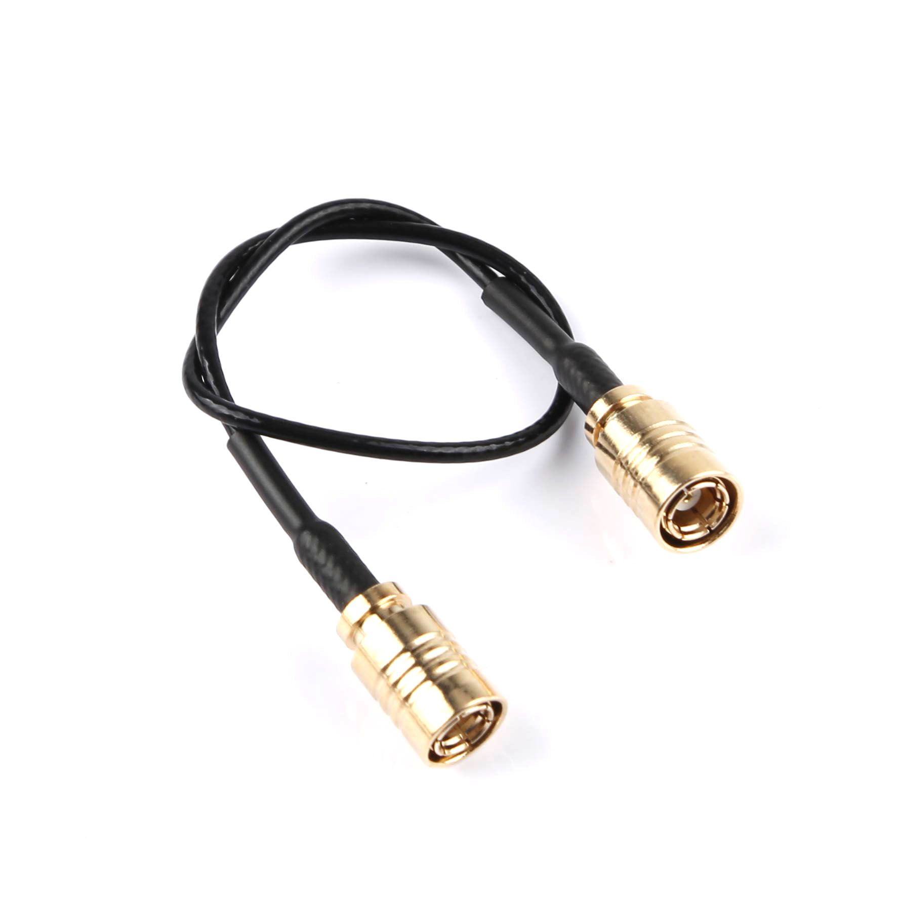
SMB cable assemblies consist of SMB connectors terminated on coaxial cables designed for radio frequency (RF) signal transmission. SMB stands for SubMiniature version B, a snap-on coaxial connector series known for its compact size, quick mating, and reliable performance up to approximately 4 GHz (with some extended designs reaching higher).
These assemblies are widely used in automotive electronics, GPS systems, telecommunications, test equipment, and other space-constrained RF applications. Unlike threaded connectors such as SMA, SMB uses a snap-on mechanism for faster connect/disconnect cycles, making it ideal for applications requiring frequent mating or blind mating.
Who This Guide Helps: Engineers selecting or assembling components for prototypes or production, and decision-makers evaluating suppliers for volume RF interconnect solutions. It is less suitable for ultra-high-frequency microwave designs (>10 GHz) or high-vibration environments without additional strain relief.
SMB Connector Basics and Key Specifications
SMB connectors typically feature 50 Ω impedance (75 Ω variants exist for specific video/broadcast uses). Standard performance includes:
Frequency range: DC to 4 GHz
Voltage rating: Around 335 V RMS
Mating cycles: Minimum 500
Coupling: Snap-on (push-to-mate, pull-to-disconnect)
Note that in SMB convention, the plug (male) often has the female receptacle contact, while the jack has the male pin—an important detail for compatibility.
Common cable types paired with SMB connectors include flexible options suited for tight routing:
RG316 SMB cable: Popular for its balance of flexibility, low loss, and durability in moderate-temperature environments.
37 SMB cableand RG1.78 SMB cable: Ultra-fine micro-coax variants for high-density, space-limited designs like internal GPS antenna routing.
These cables maintain 50 Ω characteristic impedance when properly terminated.
Common SMB Cable Configurations and Applications
SMB Male to SMB Male Cable: Straightforward interconnects for extending RF paths between modules. SMB Female to SMB Male Cable: Often used as extension or adapter cables. SMB Female to SMB Female Cable: Useful for linking male-ended equipment.
GPS Antenna SMB Cable assemblies are particularly common in automotive and navigation systems, where compact, reliable signal transfer from antenna to receiver is critical. RG174/RG316 or 1.37mm variants provide the necessary flexibility for vehicle installations.
In automotive electronics, SMB assemblies support infotainment, telematics, and sensor connections where vibration resistance and compact form factor matter.
How to Select the Right SMB Cable Assembly
Consider these decision factors:
Frequency and Loss Budget: Verify the assembly's insertion loss across your operating band. Shorter lengths and larger cable diameters (e.g., RG316 vs. RG1.37) reduce attenuation.
Environmental Conditions: Temperature range (-55°C to +165°C typical), vibration, and exposure. Use double-shielded or more robust jackets where needed.
Mechanical Constraints: Bend radius, cable flexibility, and connector orientation (straight vs. right-angle).
Power Handling and Impedance Matching: Ensure 50 Ω consistency end-to-end to minimize reflections (VSWR).
Volume and Customization: For production, evaluate supplier capabilities for custom lengths, labeling, and testing.
Verification Tip: Request VSWR, insertion loss, and return loss data from the manufacturer for your specific frequency and length. You can verify basic continuity and impedance with a vector network analyzer (VNA) or time-domain reflectometer (TDR) if available.
Step-by-Step SMB Cable Assembly Best Practices
Pre-Assembly Checks:
Select compatible cable and connector (e.g., crimp or solder type matched to RG316 or RG1.37).
Gather tools: Precision cable stripper, crimp tool with correct dies, heat gun for shrink tubing, and calipers for measurements.
Work in a clean environment to avoid contamination.
Typical Crimp Assembly Process (for common clamp/crimp SMB connectors):
Slide heat-shrink tubing and ferrule onto the cable.
Strip the cable to manufacturer-specified dimensions (center conductor, dielectric, braid—avoid nicking).
Flare or trim the braid evenly.
Insert into connector, ensuring proper seating of center conductor and braid contact.
Crimp the ferrule using the correct tool and die set.
Apply heat shrink for strain relief and insulation.
Always follow the specific connector manufacturer's assembly instructions, as dimensions vary slightly by cable type (RG316, RG178 equivalents, etc.).
Expected Results: Secure mechanical connection with no exposed braid or dielectric gaps, and stable electrical performance.
Verification: Perform a visual inspection, tug test for retention, and electrical tests (continuity, insulation resistance, VSWR if equipped).
Common Failure Signals and Diagnosis:
High VSWR or signal loss: Check for improper stripping, poor crimp, or damage.
Intermittent connection: Misalignment or insufficient braid contact—re-terminate.
Mechanical pull-out: Insufficient crimp force or wrong ferrule.
Comparison of Popular SMB Cable Types
Cable Type
Key Strengths
Best For
Considerations
RG316
Good flexibility, moderate loss
General RF, GPS extensions
Larger diameter than micro-coax
RG1.37
Ultra-compact, high density
Internal board-to-antenna routing
Higher loss over long runs
RG1.78
Balance of size and performance
Automotive, tight spaces
Similar to RG316 variants
Choose based on your loss budget and routing needs. Shorter runs favor smaller cables.
What Is a Female Header? Types, Uses, and PCB Selection Guide
2026-06-11
29
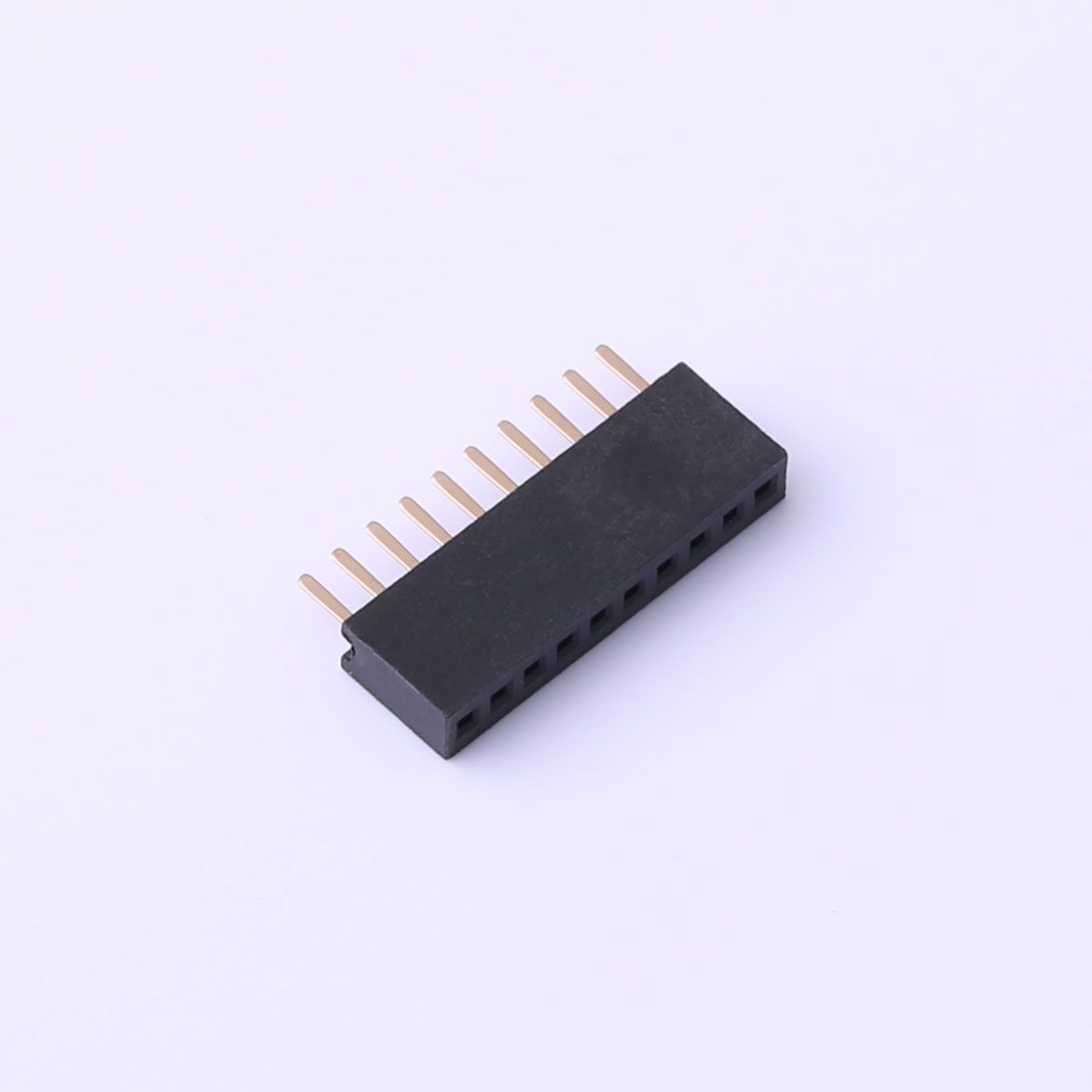
A female header connector is a PCB or cable connector whose contacts are hollow sockets — designed to receive the pins of a mating male header. It is one of the most common interconnect components in electronics, found everywhere from Arduino shields to industrial control boards.
This guide is for: PCB designers, embedded systems engineers, and makers who need to understand, select, or solder female headers correctly.
Not covered: High-current power connectors, RF/coaxial connectors, or crimp-tool assembly of wire harnesses — these fall outside the standard pin-header family and have separate selection criteria.
What Is a Female Header?
A female header consists of a row (or grid) of spring-loaded socket contacts housed in a plastic insulator body. Each socket is sized to receive a standard male pin. The term "female" describes the receptive contact geometry — the pin inserts into the socket — consistent with IEC 60050-151 general connector terminology.
Three parameters you must confirm before ordering any female header PCB component:
Pitch:center-to-center distance between adjacent contacts. The global standard for general-purpose headers is 54 mm (0.1 inch); 2.00 mm and 1.27 mm are common in compact designs.
Pin count and row count:single-row (1×N) or double-row (2×N).
Contact plating:tin plating suits most signal/low-frequency applications; gold plating improves reliability in low-current or high-cycle-count connections.
Female Header Types
Choosing the wrong type is a common and avoidable design error. The table below covers the main female header types found in production and prototyping:
Type
Configuration
Typical Application
Single-row (SIL)
1×N sockets
GPIO breakouts, edge connectors
Double-row (DIL)
2×N sockets
IC sockets, dense board-to-board links
Right-angle
Contacts exit at 90° to PCB
Panel-edge access, low-profile enclosures
SMD (surface-mount)
Solders to surface pads
High-density layouts, automated assembly
Stackable / low-profile
Extended insulator body
Arduino-style shield stacking
Wire-to-board housing
Off-board, crimped terminals
Cable harnesses, peripheral wiring
Pitch and type are independent variables — always confirm both against your mating male header's datasheet before placing an order.
What Is a Female Header Connector Used For?
Female header connectors serve three primary functions:
Board-to-board stacking.A female header on a base board accepts a male header on a daughter board, enabling modular, reversible expansion. The Arduino shield ecosystem is the most widely recognized example of this pattern.
Module-to-board interfacing.Sensor modules, display modules, and wireless modules typically ship with male pin headers. Soldering a female header onto a carrier PCB lets you swap or replace modules without desoldering — a significant advantage during prototyping and field maintenance.
Cable-to-board connections.Female housing connectors (Dupont-style or JST-compatible) terminate flying leads for connecting peripherals. This approach is common in low-to-mid volume production where connectorized cables simplify assembly and service.
Female Header vs. Male Header
Attribute
Female Header
Male Header
Contact geometry
Socket (receives pin)
Pin (inserts into socket)
Exposed metal when unmated
No — contacts recessed
Yes — pins exposed
Short-circuit risk when unmated
Lower
Higher
Rework ease
Moderate
Easier (pins visible)
Typical PCB role
Receiving / mating side
Source / plug side
Placement convention: There is no universal rule mandating which gender goes on which board. A common engineering practice is to place the female (recessed) connector on the side that carries a live power rail when unmated, since the recessed geometry reduces accidental short-circuit risk. Your specific mechanical layout and safety requirements should drive the final decision — not convention alone.
How to verify your placement choice: Before finalizing layout, check whether the unmated connector will be accessible to a user or exposed in the enclosure. If so, the recessed female contact reduces — though does not eliminate — shock and short-circuit hazard. Confirm against your product's applicable safety standard (e.g., IEC 60950-1 / IEC 62368-1 for IT and AV equipment).
How to Solder Female Header Pins
This procedure applies to through-hole female headers on standard FR4 PCBs. SMD variants require controlled reflow and are outside this scope.
Prerequisites:
Temperature-controlled soldering iron (320–370 °C for leaded solder; 340–380 °C for lead-free SAC305)
Solder wire, 0.8–1.0 mm diameter
No-clean or rosin-core flux
PCB with correct footprint (hole diameter ~0.9–1.0 mm for 2.54 mm pitch standard headers)
PCB holder or helping hands
Steps:
Dry-fit first.Insert the header into the footprint without solder. It should seat flush with no forcing. A tight fit suggests an incorrect hole size — stop and verify the footprint before proceeding.
Tack one corner pin.Apply a small solder amount to a single end pin while holding the header flush. This anchors position for the remaining pins.
Check perpendicularity.Inspect from both the side and front. Reheat the tack joint and adjust if the header is tilted — this is your last easy correction point.
Solder remaining pins sequentially.Place the iron tip at the pin/pad junction for approximately 2 seconds, then feed solder wire into the joint (not onto the iron tip). A good joint is shiny, smooth, and forms a concave fillet that wets both pin and pad annular ring.
Inspect every joint.Use a magnifier or phone camera. Reject joints that are: dull or grainy (cold joint), balled up without pad wetting (insufficient heat), or bridging to an adjacent pin.
Clean flux residueper your product's requirements. No-clean flux is acceptable in many assemblies per IPC-A-610 guidelines, but confirm with your quality specification.
Failure signals and what they indicate:
Intermittent connection after mating:likely a cold joint — reflow with added flux
Header tilted after full soldering:tack joint cooled before alignment check — desolder, clean, and restart from step 2
Solder bridges between pins:remove with solder wick and flux, re-inspect under magnification
How to verify: After soldering, use a multimeter in continuity mode to confirm each pin connects to its intended net. For applications with repeated mating cycles (>50), a brief functional insertion/removal test under operating conditions can reveal marginal mechanical joints before the board ships.
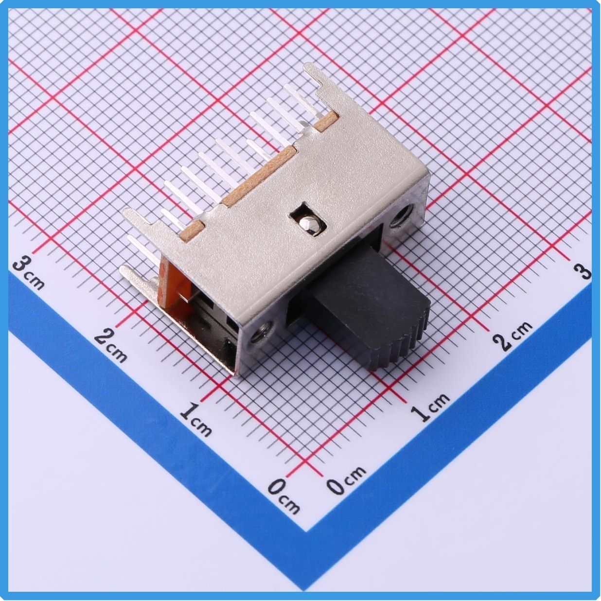
『Product Highlight』Kinghelm Slide Switch KH-SS23F19-G8: Reliable DP3T Multi-Position Control for Precision Signal Switching
2026-06-11
17
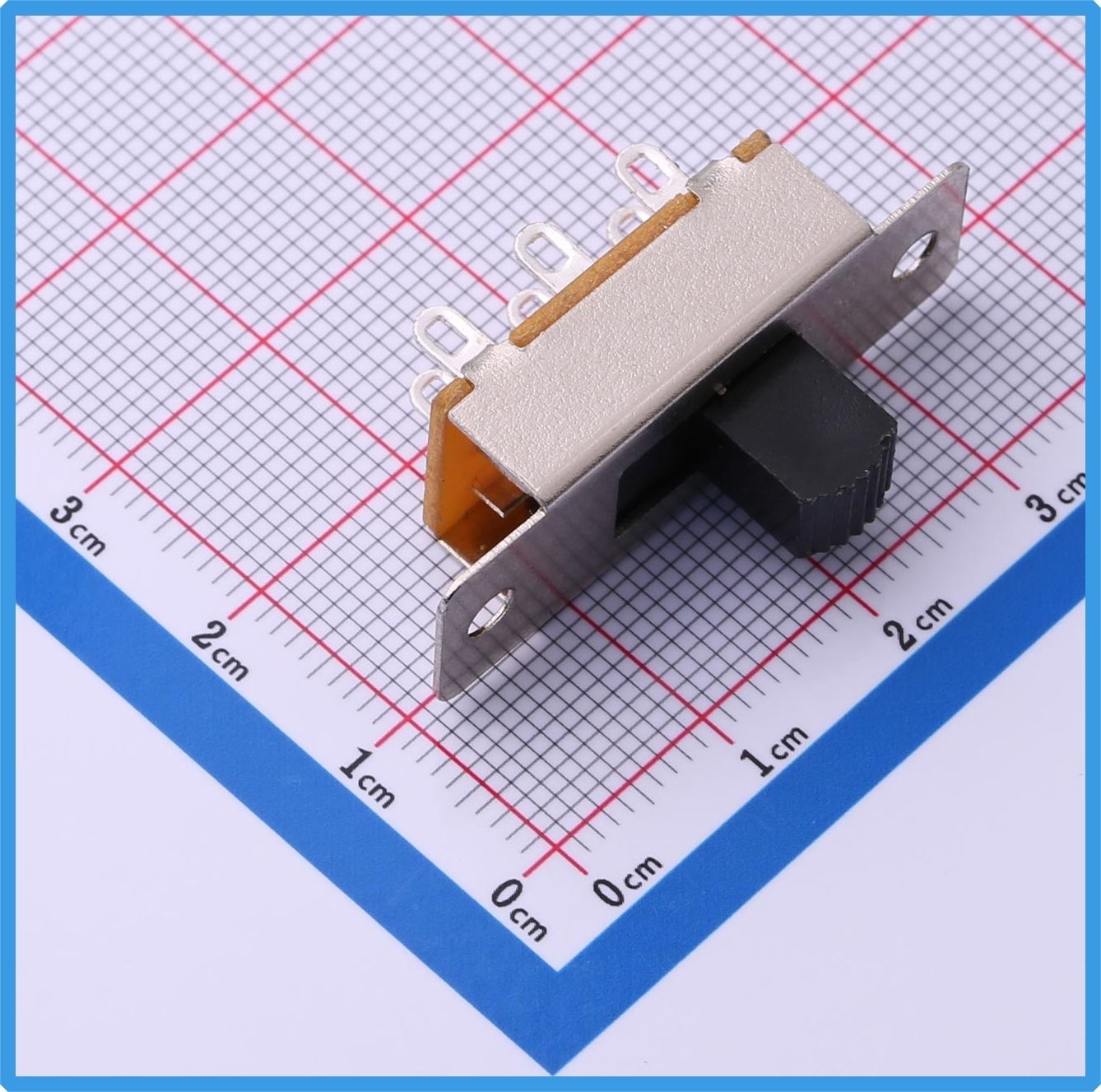
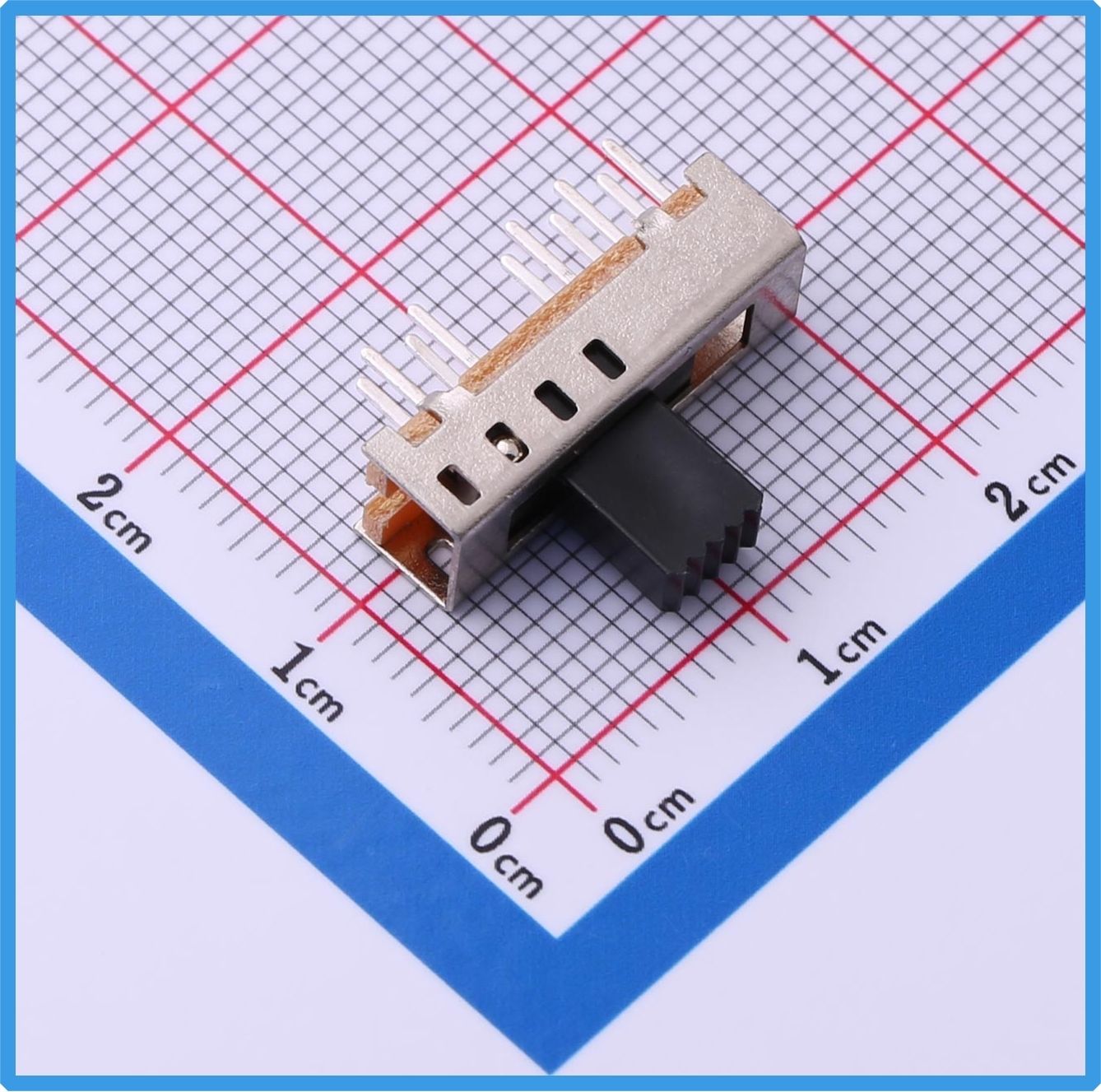
In modern electronic product design, control components are expected to be both compact and highly reliable, especially in applications requiring multi-function switching. The Kinghelm KH-SS23F19-G8 slide switch is a DP3T (double-pole triple-throw) switch designed to deliver stable three-position control with clear tactile feedback and strong mechanical durability. With a through-hole mounting structure and solder lug terminals, this model ensures secure electrical connections and long-term stability. Its compact body size of 35.3mm × 13mm, combined with a black rectangular slider design, makes it suitable for a wide range of industrial and consumer electronics. Whether used in audio systems, instrumentation, or industrial control panels, this switch provides a dependable solution for multi-circuit selection and signal routing.
Kinghelm KH-SS23F19-G8 Product Image
DP3T Structure for Flexible Three-Position Switching
The KH-SS23F19-G8 adopts a DP3T circuit configuration, allowing two independent circuits to be switched across three positions. This structure enables flexible signal routing and functional mode selection within a single component, making it highly suitable for systems requiring multiple operational states.
The rectangular slider design ensures smooth operation with distinct position feedback, allowing users to clearly identify switching states during use. In addition, the solder lug terminals increase the contact area between the switch and PCB, improving solder joint strength and reducing the risk of poor connectivity over long-term operation or vibration environments.
As part of the Kinghelm slide switch series, this model emphasizes both electrical stability and mechanical reliability, making it suitable for designs requiring consistent switching performance in mass production.
Wide Application Across Audio, Industrial, and Communication Systems
The KH-SS23F19-G8 slide switch is widely used across multiple electronic fields due to its stable multi-position switching capability.
In audio equipment such as amplifiers and sound systems, it is commonly used for input selection, sound mode switching, and signal routing control. Its clear three-position structure allows intuitive user interaction and precise function control.
In industrial control systems, the switch is used for mode selection, operational state switching, and functional segmentation of equipment. Its durable mechanical structure makes it suitable for environments requiring frequent operation or long service life.
It is also widely applied in instrumentation and communication devices, where reliable signal switching between different operating modes is essential. Additionally, in security systems, it supports stable configuration selection under continuous working conditions.
Backed by Kinghelm manufacturing expertise in electronic connectors and switches, this product ensures consistent quality and stable performance across large-scale production applications.
Engineering Advantages and Installation Reliability
From an engineering perspective, the KH-SS23F19-G8 is designed not only for functional switching but also for practical PCB integration and long-term durability.
Its 35.3mm × 13mm form factor provides a clear reference for PCB layout design, making it easier for engineers to allocate space during system integration. The through-hole mounting structure ensures strong mechanical fixation, while the solder lug terminals enhance structural stability during assembly and operation.
The switch is designed to withstand repeated mechanical cycling, making it suitable for applications requiring frequent switching actions. Its stable contact design reduces signal interruption risks, ensuring reliable circuit performance over time.
In mass production environments, the consistent dimensional accuracy of Kinghelm slide switches helps improve assembly efficiency and reduces variability between units, which is critical for industrial-grade electronic manufacturing.
Kinghelm KH-SS23F19-G8 Specification
Conclusion: A Practical and Reliable Choice for Multi-Position Control
The Kinghelm KH-SS23F19-G8 slide switch combines a DP3T structure, durable through-hole design, and stable solder lug connections to deliver a reliable multi-position switching solution for modern electronic systems.
Whether used in audio equipment, industrial controllers, or communication devices, it provides consistent performance and clear operational feedback. For engineers and product designers seeking a dependable slide switch for multi-functional control applications, this model represents a practical and production-ready option.
For more electronic components and switching solutions from Kinghelm , exploring the full product range can help optimize your system design with stable and efficient control elements.
About Kinghelm
Shenzhen Kinghelm Electronics Co., Ltd.(www.kinghelm.net)has technical backbones from Tsinghua University and UESTC, and has introduced overseas returnee professionals. Kinghelm is able to develop highly reliable and high-performance antenna and connector products.KH series products of "Kinghelm" brand include Beidou/GPS antennas, RF adapter connectors, plug connector, electrical data connectors, terminals, and customized vehicle harnesses, industrial / medical connectors, and special antenna connectors."Kinghelm connects world", Kinghelm has grown with the development of China's Beidou industry. Starting from supplying Beidou/GPS dual mode antennas, IPEX terminals, and RF adapter cables for automotive manufacturers, Kinghelm has continuously developed products. Currently, it has a series of WiFi, Bluetooth, NB-loT, LoRa, Zigbee, UWB, and GSM antennas, RFID tags, RF adapter cables, standard microwave antennas, vehicle grade SMA, SMB, FAKRA holders, coaxial cables, and can customize non-standard antenna connectors based on customer drawings or samples.
KH-SS23F19-G8View Product Details
『Product Highlight』Kinghelm Slide Switch KH-SS24H20-G10: Precise 4-Position Switching for Seamless Multi-Mode Control
2026-06-10
21
As modern electronic devices continue to evolve toward greater intelligence and functionality, the demand for versatile control components has increased significantly. Traditional single-position or dual-position switches are often insufficient for systems requiring multiple operating modes. This is where multi-position slide switches play a crucial role.
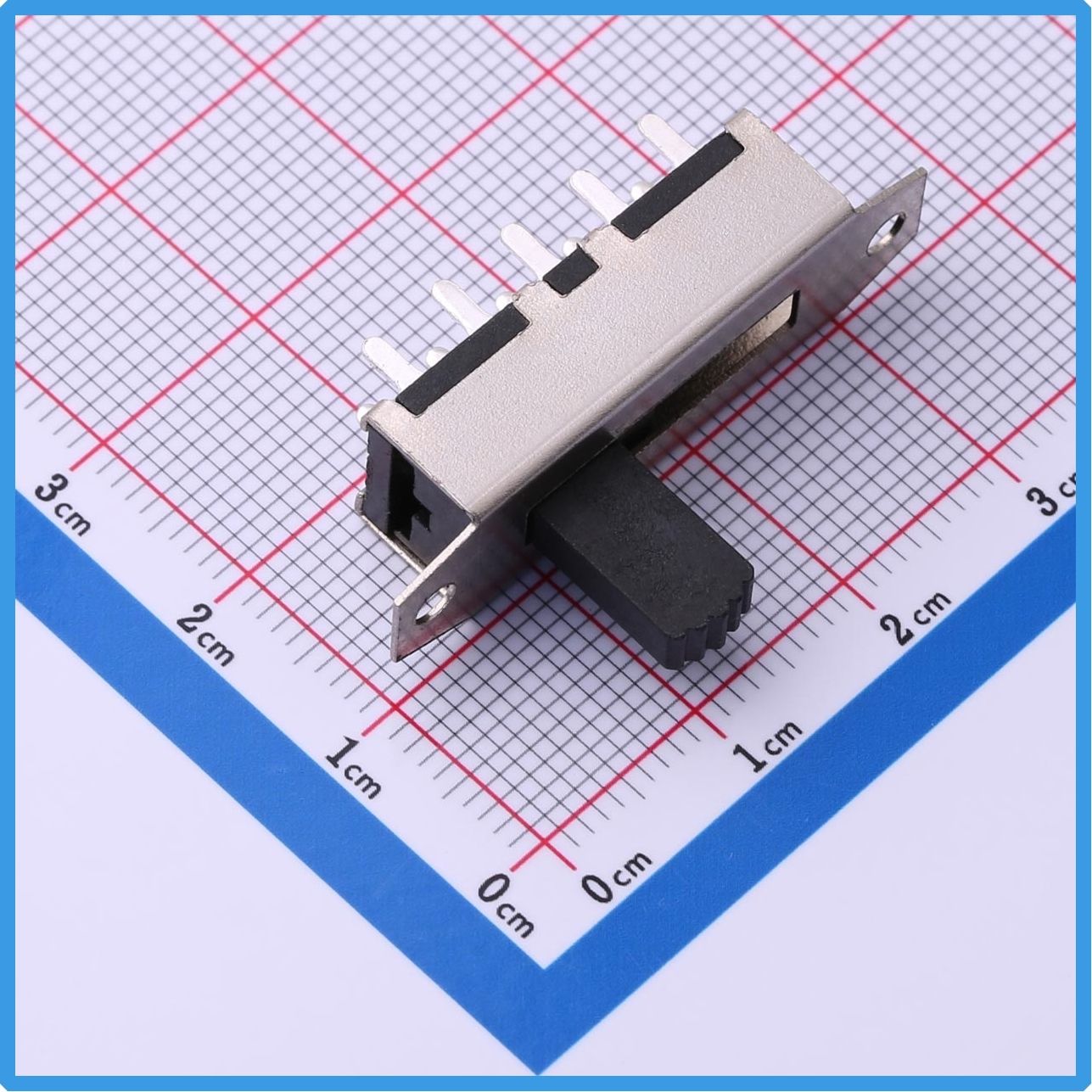
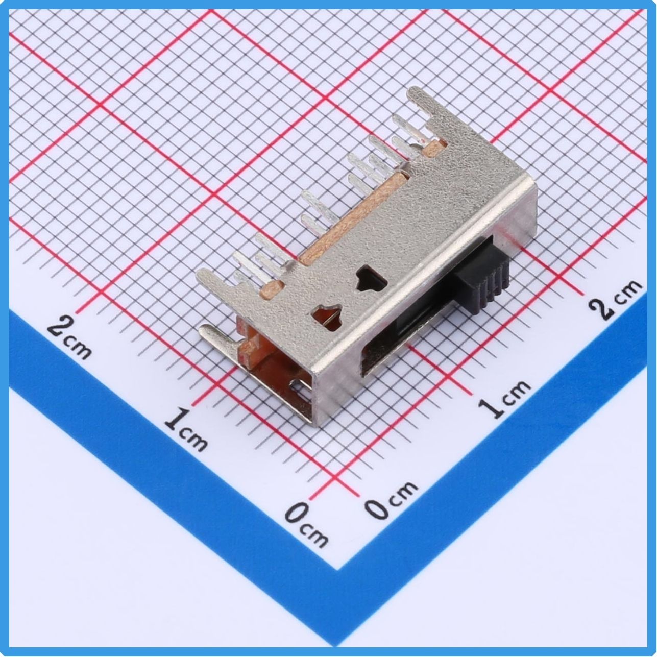
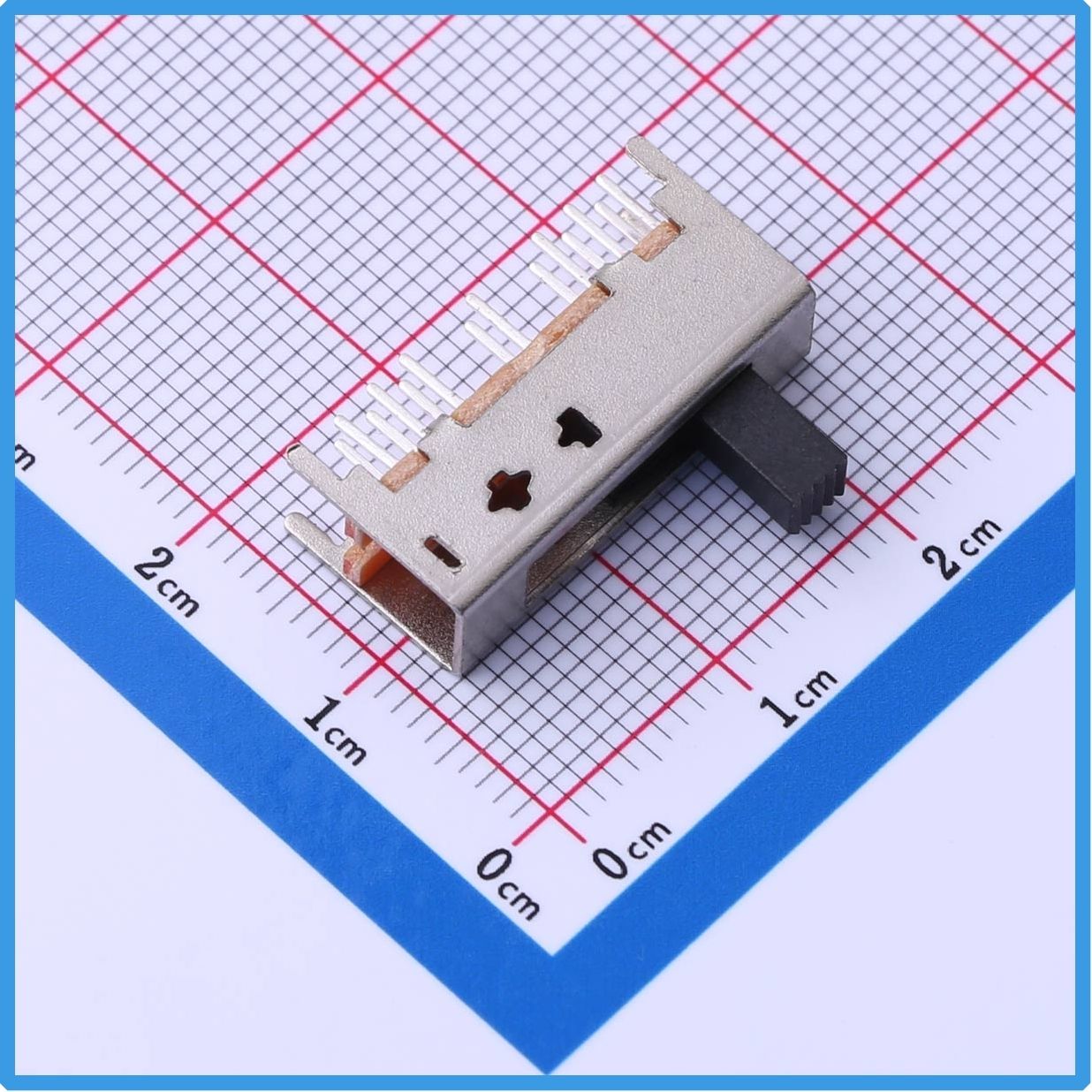
The Kinghelm KH-SS24H20-G10 Vertical Slide Switch is specifically designed to provide stable and accurate multi-state control. Featuring a Double Pole Four Position (DP4T) configuration and a non-shorting switching mechanism, this switch offers dependable performance for industrial equipment, communication systems, test instruments, consumer electronics, and various intelligent control applications.
With its compact structure, reliable contact performance, and clear switching feedback, the KH-SS24H20-G10 has become an ideal choice for engineers seeking efficient mode selection and circuit control solutions.
Kinghelm KH-SS24H20-G10 Product Image
Multi-Position Switching for Enhanced Functionality
Electronic products today often require multiple operating modes to accommodate different user requirements and application scenarios. The Kinghelm KH-SS24H20-G10 addresses this need through its DP4T (Double Pole Four Position) design, enabling four distinct switching states within a single component.
This configuration allows designers to implement multiple functions without increasing PCB complexity. Whether selecting operating modes, changing communication settings, configuring parameters, or switching signal paths, the switch provides precise and reliable control.
The 4mm actuator travel delivers clear tactile feedback during operation, allowing users to easily identify position changes. This enhances both usability and operational accuracy in professional equipment and consumer devices.
Unlike shorting-type switches, the KH-SS24H20-G10 utilizes a non-shorting contact structure. During transition between positions, electrical contacts remain isolated, preventing unintended circuit connections. This feature is particularly important in applications where accidental signal overlap or temporary short circuits could affect system performance.
As a result, the switch offers greater reliability in sensitive electronic systems and precision control applications.
Compact Design with Secure Through-Hole Installation
Space efficiency remains a critical factor in modern PCB design. The KH-SS24H20-G10 features a compact body measuring approximately 18.2mm × 10.5mm, with an overall length of 25mm. This allows designers to integrate advanced switching functionality while minimizing board space consumption.
The switch adopts a vertical through-hole mounting structure, providing strong mechanical stability after soldering. Compared with some surface-mounted alternatives, through-hole installation offers improved resistance to vibration and mechanical stress, making it suitable for demanding industrial environments.
Its dual-row pin layout enhances solder joint reliability and ensures stable electrical performance over long periods of operation. The standardized pin arrangement also supports efficient assembly processes, making the component suitable for both manual production and automated manufacturing lines.
Kinghelm places strong emphasis on product consistency and manufacturing quality, ensuring that each switch delivers dependable performance throughout its service life.
Ideal for Industrial, Communication, and Consumer Electronics
One of the key advantages of the KH-SS24H20-G10 is its broad application compatibility.
In industrial automation systems, the switch can be used for operating mode selection, parameter configuration, and control panel functions. Test and measurement equipment can utilize its four-position capability for range selection, signal routing, or operational settings.
Communication devices frequently require switching between different modes, channels, or configurations. The non-shorting design of the KH-SS24H20-G10 helps maintain signal integrity and system stability during these transitions.
In consumer electronics, the switch is suitable for audio devices, smart home controllers, portable instruments, gaming peripherals, and various electronic products requiring multi-level functionality.
As electronic products continue to integrate more features into compact designs, reliable multi-position switches like the KH-SS24H20-G10 are becoming increasingly valuable components for system designers worldwide.
Design Considerations for Optimal Performance
To maximize the performance and reliability of the KH-SS24H20-G10, several design considerations should be taken into account during PCB development.
The PCB footprint should match the switch dimensions and accommodate the approximately 18mm soldering area with a 6.5mm dual-row pin center spacing. Proper mechanical support should also be incorporated to ensure stable installation.
Adequate clearance around the actuator should be reserved to allow smooth user operation and prevent enclosure interference. This is especially important in compact electronic devices where external housing components may limit switch movement.
Engineers should also ensure that the switch is operated within its specified electrical ratings. Proper circuit design and load management will help extend operational life and maintain long-term performance consistency.
By following recommended installation practices, manufacturers can achieve optimal reliability and durability in their final products.
Why Choose Kinghelm KH-SS24H20-G10?
Kinghelm has established itself as a trusted supplier of electronic components, connectors, RF antennas, switches, and interconnection solutions. The company's commitment to quality, innovation, and manufacturing excellence has earned recognition across numerous industries.
The KH-SS24H20-G10 reflects these strengths through its:
Double Pole Four Position (DP4T) switching capability
Non-shorting contact design
Clear 4mm actuator travel
Vertical through-hole mounting structure
Reliable dual-row pin configuration
Compact dimensions for efficient PCB utilization
Stable performance in demanding applications
These features make it an excellent choice for engineers seeking dependable multi-position switching solutions.
Kinghelm KH-SS24H20-G10 Specification
Conclusion
The Kinghelm KH-SS24H20-G10 Vertical Slide Switch combines flexible four-position control, reliable non-shorting operation, compact construction, and robust mechanical design into a single component. Whether used in industrial automation, communication equipment, testing instruments, or consumer electronics, it provides an effective solution for multi-mode selection and circuit control.
As modern electronic systems continue to demand greater functionality and reliability, the KH-SS24H20-G10 stands out as a practical and dependable switching solution. For engineers and manufacturers looking to improve control flexibility while maintaining system stability, this Kinghelm slide switch represents a smart and efficient choice.
About Kinghelm
Shenzhen Kinghelm Electronics Co., Ltd.(www.kinghelm.net)has technical backbones from Tsinghua University and UESTC, and has introduced overseas returnee professionals. Kinghelm is able to develop highly reliable and high-performance antenna and connector products.KH series products of "Kinghelm" brand include Beidou/GPS antennas, RF adapter connectors, plug connector, electrical data connectors, terminals, and customized vehicle harnesses, industrial / medical connectors, and special antenna connectors."Kinghelm connects world", Kinghelm has grown with the development of China's Beidou industry. Starting from supplying Beidou/GPS dual mode antennas, IPEX terminals, and RF adapter cables for automotive manufacturers, Kinghelm has continuously developed products. Currently, it has a series of WiFi, Bluetooth, NB-loT, LoRa, Zigbee, UWB, and GSM antennas, RFID tags, RF adapter cables, standard microwave antennas, vehicle grade SMA, SMB, FAKRA holders, coaxial cables, and can customize non-standard antenna connectors based on customer drawings or samples.
『Product Highlight』Kinghelm Slide Switch KH-SS24E01-G6: Compact Design for Reliable Signal Switching
2026-06-09
31
As electronic devices continue to become smaller, smarter, and more integrated, engineers are placing greater emphasis on component size, reliability, and installation flexibility. Among various control components, slide switches remain a popular choice due to their simple operation, dependable performance, and cost-effective design.
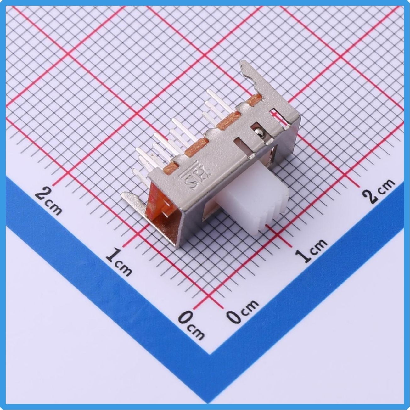
The Kinghelm KH-SS24E01-G6 Slide Switch is designed to provide stable signal switching in compact electronic applications. Featuring a vertical through-hole structure and a shorting contact mechanism, this slide switch offers smooth operation, reliable electrical performance, and efficient space utilization. It is widely used in consumer electronics, communication equipment, industrial control systems, and various electronic devices that require dependable switching functions.
Kinghelm KH-SS24E01-G6 Product Image
Compact Structure Optimized for Modern PCB Designs
As electronic products become increasingly compact, PCB space has become one of the most valuable resources in product development. Designers are constantly searching for components that deliver functionality while occupying minimal board space.
The KH-SS24E01-G6 Slide Switch features a compact body with an overall length of 18.1mm, a width of 6.2mm, and a base height of 5.2mm. Its small footprint allows engineers to optimize PCB layouts and integrate more functions within limited space.
The vertical through-hole mounting design further improves installation flexibility and mechanical stability. This makes the switch particularly suitable for portable devices, communication modules, compact control boards, and space-constrained electronic systems.
In addition to its compact size, the switch is engineered for smooth operation and long-term durability, helping manufacturers enhance overall product quality and reliability.
Shorting Contact Design for Smooth Signal Transition
One of the key features of the KH-SS24E01-G6 is its shorting contact mechanism, also known as a make-before-break design. During switching, electrical contacts briefly overlap, allowing signals to transition smoothly between positions.
This design helps reduce the risk of signal interruption and improves overall system stability. For applications such as communication devices, audio equipment, and electronic control systems, maintaining continuous signal flow can be critical to performance.
The switch provides a smooth sliding action with clear tactile feedback, allowing users to operate it easily and accurately. Whether used in frequently operated consumer products or long-life industrial equipment, the KH-SS24E01-G6 delivers dependable switching performance.
As electronic systems continue to demand higher reliability, shorting slide switches remain a preferred solution for many signal control applications.
Reliable Performance for Long-Term Applications
Reliability is one of the most important considerations when selecting electronic components. A high-quality slide switch can significantly improve the stability and service life of the entire system.
The KH-SS24E01-G6 is built with a durable mechanical structure designed to withstand repeated operation while maintaining consistent electrical performance. Its standardized pin layout simplifies PCB design and supports efficient assembly processes.
Kinghelm maintains strict quality control standards throughout manufacturing to ensure product consistency and dependable performance. This commitment to quality helps equipment manufacturers reduce maintenance costs and improve end-user satisfaction.
For businesses seeking reliable electronic switching components, the KH-SS24E01-G6 provides an effective balance between performance, durability, and cost efficiency.
Suitable for a Wide Range of Electronic Applications
Thanks to its compact size and stable operation, the KH-SS24E01-G6 Slide Switch is suitable for a wide variety of electronic applications.
In consumer electronics, it can be used for function selection and control operations. In communication equipment, it supports signal routing and device configuration. Industrial control systems can utilize the switch for operational settings and control functions, while compact electronic modules benefit from its space-saving design.
Its versatility makes it an excellent choice for manufacturers seeking a dependable switching solution across multiple product categories.
As demand for compact and reliable electronic devices continues to grow, the need for high-quality slide switches remains strong. The KH-SS24E01-G6 is designed to meet these evolving market requirements.
Kinghelm KH-SS24E01-G6 Specification
Conclusion
The Kinghelm KH-SS24E01-G6 Slide Switch combines compact dimensions, reliable switching performance, and a space-saving vertical mounting design to meet the needs of modern electronic products.
Whether used in consumer electronics, communication systems, industrial equipment, or embedded control devices, this slide switch provides stable operation and long-term reliability. For engineers and manufacturers looking for a compact and dependable switching solution, the KH-SS24E01-G6 is a practical choice that supports efficient product design and consistent performance.
Explore more high-quality electronic components from Kinghelm and discover reliable solutions for your next project.
About Kinghelm
Shenzhen Kinghelm Electronics Co., Ltd.(www.kinghelm.net)has technical backbones from Tsinghua University and UESTC, and has introduced overseas returnee professionals. Kinghelm is able to develop highly reliable and high-performance antenna and connector products.KH series products of "Kinghelm" brand include Beidou/GPS antennas, RF adapter connectors, plug connector, electrical data connectors, terminals, and customized vehicle harnesses, industrial / medical connectors, and special antenna connectors."Kinghelm connects world", Kinghelm has grown with the development of China's Beidou industry. Starting from supplying Beidou/GPS dual mode antennas, IPEX terminals, and RF adapter cables for automotive manufacturers, Kinghelm has continuously developed products. Currently, it has a series of WiFi, Bluetooth, NB-loT, LoRa, Zigbee, UWB, and GSM antennas, RFID tags, RF adapter cables, standard microwave antennas, vehicle grade SMA, SMB, FAKRA holders, coaxial cables, and can customize non-standard antenna connectors based on customer drawings or samples.
『Product Highlight』Kinghelm Slide Switch KH-SS25D01-G2: Reliable Dual-Circuit Control for Modern Electronic Devices
2026-06-08
19
In today's rapidly evolving electronics industry, even a small switching component can significantly impact the performance, usability, and reliability of an electronic device. From consumer electronics and industrial automation systems to communication equipment and testing instruments, engineers require switching solutions that offer stable operation, long service life, and precise control. As one of the essential components in electronic circuit design, slide switches remain widely used due to their simple structure, intuitive operation, and dependable performance.
The Kinghelm KH-SS25D01-G2 Slide Switch is designed to meet these demands. Featuring a dual-circuit control design, vertical through-hole mounting, and a compact 2-position sliding mechanism, this switch provides efficient and reliable circuit control for a wide range of electronic applications. Its robust metal housing and precise switching performance make it an ideal choice for modern electronic equipment requiring dependable mode selection and circuit switching functions.
Kinghelm KH-SS25D01-G2 Product Image
Dual-Circuit Switching Design for Flexible Control
The KH-SS25D01-G2 utilizes a dual-circuit switching structure, enabling simultaneous control of two independent circuits. Compared with simpler single-circuit switches, this design offers greater flexibility and functionality, making it suitable for more versatile electrical control systems.
With its 2-position sliding mechanism and 2mm travel distance, the switch allows users to quickly and accurately change operating modes. The carefully engineered sliding action provides clear tactile feedback while minimizing the possibility of accidental switching.
For designers seeking efficient multi-function control solutions, the KH-SS25D01-G2 simplifies circuit layouts and reduces the number of additional switching components required. This contributes to lower system complexity and improved overall design efficiency.
Whether used for signal routing, function selection, or operational mode switching, the switch delivers reliable performance across various electronic applications.
Vertical Through-Hole Mounting Enhances Installation Reliability
Manufacturing efficiency and assembly reliability are increasingly important considerations in modern electronics production. The KH-SS25D01-G2 adopts a vertical through-hole (DIP) mounting design, offering excellent soldering stability and mechanical strength.
The switch measures 18.5mm in overall length and features a compact body width of only 6.6mm. This space-saving design helps engineers maximize PCB utilization while maintaining sufficient operating accessibility.
Compared with some surface-mount alternatives, through-hole mounting provides stronger mechanical retention and improved resistance to vibration and physical stress. This makes the switch particularly suitable for industrial equipment, communication devices, and applications where long-term durability is essential.
Additionally, the vertical installation structure allows greater flexibility in product enclosure and panel design, making it easier to integrate into a variety of electronic systems.
Durable Metal Housing Improves Reliability and Protection
Electronic devices often operate in environments where vibration, impact, frequent operation, and electromagnetic interference may affect component performance. To address these challenges, the KH-SS25D01-G2 features a fully enclosed metal housing that enhances both durability and operational stability.
The metal casing protects internal contacts from external influences while increasing the switch's structural strength. This robust design helps maintain reliable performance throughout transportation, assembly, and long-term operation.
The black actuator is manufactured from POM (Polyoxymethylene) engineering plastic, known for its excellent wear resistance, dimensional stability, and mechanical properties. Even after repeated switching cycles, the actuator maintains smooth and consistent operation.
Furthermore, the optimized internal contact structure ensures dependable electrical connectivity during every switching action. Stable contact performance helps reduce the risk of signal interruption or circuit malfunction, contributing to the overall reliability of the electronic system.
Wide Range of Applications Across Multiple Industries
Thanks to its compact dimensions and durable construction, the KH-SS25D01-G2 is suitable for numerous applications across different industries.
In consumer electronics, it can be used for power selection, operating mode switching, and functional control in products such as Bluetooth speakers, remote controls, gaming devices, and small household appliances.
In communication equipment, the switch supports signal routing, system configuration, and operational mode selection for network devices and wireless terminals.
For industrial control systems, it serves as a reliable solution for parameter settings, circuit switching, and equipment operation management.
In test and measurement instruments, the switch enables accurate signal path selection and function control, supporting efficient and reliable device operation.
As smart devices, IoT products, and automation systems continue to expand globally, demand for dependable switching components is increasing. The KH-SS25D01-G2 provides engineers with a practical and reliable solution that meets the evolving requirements of modern electronic design.
To achieve optimal performance, proper soldering practices should be followed during installation. Engineers should ensure accurate pin alignment, avoid applying excessive force to the actuator, and provide adequate clearance for smooth operation throughout the full 2mm switching travel.
Kinghelm KH-SS25D01-G2 Specification
Conclusion
The Kinghelm KH-SS25D01-G2 Slide Switch combines dual-circuit switching capability, a compact vertical through-hole design, durable metal housing, and smooth two-position operation to deliver dependable circuit control for a wide variety of electronic devices. Whether used in consumer electronics, industrial automation, communication systems, or measurement equipment, this slide switch provides stable and efficient switching performance.
As a trusted electronic component manufacturer, Kinghelm continues to develop high-quality connectivity and control solutions for global customers. The KH-SS25D01-G2 exemplifies Kinghelm's commitment to reliability, functionality, and engineering excellence, making it an excellent choice for designers seeking dependable slide switch solutions in modern electronic applications.
About Kinghelm
Shenzhen Kinghelm Electronics Co., Ltd.(www.kinghelm.net)has technical backbones from Tsinghua University and UESTC, and has introduced overseas returnee professionals. Kinghelm is able to develop highly reliable and high-performance antenna and connector products.KH series products of "Kinghelm" brand include Beidou/GPS antennas, RF adapter connectors, plug connector, electrical data connectors, terminals, and customized vehicle harnesses, industrial / medical connectors, and special antenna connectors."Kinghelm connects world", Kinghelm has grown with the development of China's Beidou industry. Starting from supplying Beidou/GPS dual mode antennas, IPEX terminals, and RF adapter cables for automotive manufacturers, Kinghelm has continuously developed products. Currently, it has a series of WiFi, Bluetooth, NB-loT, LoRa, Zigbee, UWB, and GSM antennas, RFID tags, RF adapter cables, standard microwave antennas, vehicle grade SMA, SMB, FAKRA holders, coaxial cables, and can customize non-standard antenna connectors based on customer drawings or samples.
『Product Highlight』Kinghelm DP6T Slide Switch KH-SS26D01-G6: Reliable Multi-Position Control for Advanced Electronic Designs
2026-06-06
20
As electronic devices continue to evolve toward greater functionality and integration, reliable switching components play a crucial role in ensuring stable circuit operation and user-friendly control. In applications requiring multiple operating modes, signal routing options, or function selection, a high-quality slide switch can significantly improve system performance and design flexibility.
The Kinghelm KH-SS26D01-G6 Vertical Through-Hole Slide Switch is designed to meet these demands. Featuring a Double Pole Six Throw (DP6T) configuration, a shorting contact mechanism, and a compact through-hole mounting structure, this switch provides engineers with a dependable solution for complex circuit control requirements across industrial, communication, instrumentation, and consumer electronic applications.
Kinghelm KH-SS26D01-G6 Product Image
DP6T Configuration Enables Flexible Multi-Position Switching
One of the key advantages of the KH-SS26D01-G6 is its Double Pole Six Throw (DP6T) circuit structure.
The switch incorporates two independent poles and six selectable positions, allowing multiple signal paths or operating modes to be controlled within a single component. Compared with conventional SPST, SPDT, or DPDT switches, the DP6T design offers significantly greater functionality while minimizing PCB space requirements.
Typical applications include:
Function selection in industrial control systems
Frequency or channel switching in communication equipment
Signal routing in audio devices
Mode selection in test and measurement instruments
Multi-state control in smart electronic products
By integrating multiple switching functions into a single component, engineers can simplify circuit architecture, reduce component count, and improve overall system efficiency.
Shorting Contact Design Ensures Continuous Signal Transfer
The KH-SS26D01-G6 adopts a SHORTING (Make-Before-Break) contact mechanism.
During position transitions, the new contact is connected before the previous contact is disconnected, creating a brief overlap that maintains circuit continuity. This design helps prevent temporary signal interruptions that may occur during switching operations.
Key benefits include:
Reduced signal interruption
Improved switching reliability
Enhanced operational stability
Minimized system glitches during mode changes
This feature is particularly valuable in communication systems, audio equipment, and industrial electronics where uninterrupted signal transmission is critical for proper operation.
By maintaining continuity during switching, the KH-SS26D01-G6 contributes to a smoother and more reliable user experience.
Compact Dimensions Support Space-Efficient PCB Designs
Modern electronic products increasingly require compact and efficient component layouts.
The KH-SS26D01-G6 is designed with a space-saving form factor:
Switch Length: 21.5 mm
Switch Width: 6.6 mm
Base Height: 10.5 mm
Actuator Type: Rectangular Lever
Terminal Style: PC Pins
Mounting Type: Vertical Through-Hole
The compact structure allows designers to optimize PCB layouts while maintaining easy accessibility for manual operation.
Its rectangular actuator provides clear tactile feedback and comfortable operation, making it suitable for products that require frequent mode selection or configuration changes.
The switch's dimensions also enable integration into devices where internal space is limited without sacrificing functionality.
Through-Hole PC Pins Improve Mechanical Stability
The KH-SS26D01-G6 utilizes PC pin terminals designed for through-hole mounting.
Compared with some surface-mount alternatives, through-hole construction offers enhanced mechanical strength and long-term reliability, particularly in demanding operating environments.
Advantages include:
Strong solder joint integrity
Excellent vibration resistance
Compatibility with wave soldering processes
Reliable electrical connections
Efficient mass production capability
The vertical mounting structure further enhances design flexibility by making effective use of available PCB space.
For industrial equipment, communication systems, and control devices where durability is essential, the through-hole design provides an additional level of operational security.
RoHS Compliant for Global Environmental Standards
Environmental compliance has become a critical requirement for electronic product manufacturing worldwide.
The Kinghelm KH-SS26D01-G6 is fully compliant with RoHS regulations, ensuring that restricted hazardous substances are controlled throughout the manufacturing process.
Benefits of RoHS compliance include:
Compliance with international environmental regulations
Support for global market access
Alignment with sustainable manufacturing practices
Enhanced product credibility for export projects
By selecting RoHS-compliant components, manufacturers can simplify certification processes and support environmentally responsible product development.
Ideal Applications Across Multiple Industries
Thanks to its DP6T architecture, shorting contact design, compact dimensions, and robust construction, the Kinghelm KH-SS26D01-G6 is suitable for a wide range of applications, including:
Industrial automation equipment
Communication devices
Test and measurement instruments
Audio and multimedia systems
Smart home products
Consumer electronics
Embedded control systems
IoT devices
Its versatility makes it an excellent choice for engineers seeking dependable multi-position switching solutions.
Kinghelm KH-SS26D01-G6 Specification
Conclusion
The Kinghelm KH-SS26D01-G6 Vertical Through-Hole Slide Switch combines a DP6T configuration, make-before-break switching mechanism, compact dimensions, and reliable through-hole mounting into a single high-performance component.
Whether used in industrial control systems, communication equipment, instrumentation, or advanced consumer electronics, this switch delivers dependable multi-position control and stable signal switching performance.
For engineers looking for a reliable and flexible slide switch solution, the Kinghelm KH-SS26D01-G6 provides an effective balance of functionality, durability, and design efficiency.
About Kinghelm
Shenzhen Kinghelm Electronics Co., Ltd.(www.kinghelm.net)has technical backbones from Tsinghua University and UESTC, and has introduced overseas returnee professionals. Kinghelm is able to develop highly reliable and high-performance antenna and connector products.KH series products of "Kinghelm" brand include Beidou/GPS antennas, RF adapter connectors, plug connector, electrical data connectors, terminals, and customized vehicle harnesses, industrial / medical connectors, and special antenna connectors."Kinghelm connects world", Kinghelm has grown with the development of China's Beidou industry. Starting from supplying Beidou/GPS dual mode antennas, IPEX terminals, and RF adapter cables for automotive manufacturers, Kinghelm has continuously developed products. Currently, it has a series of WiFi, Bluetooth, NB-loT, LoRa, Zigbee, UWB, and GSM antennas, RFID tags, RF adapter cables, standard microwave antennas, vehicle grade SMA, SMB, FAKRA holders, coaxial cables, and can customize non-standard antenna connectors based on customer drawings or samples.
『Product Highlight』Kinghelm Slide Switch KH-SS33E05-G5: Silver-Plated Contacts for Reliable Industrial and Electronic Control
2026-06-05
22
In today's rapidly evolving electronics industry, the reliability of even the smallest component can significantly impact the performance of an entire device. Among these components, slide switches play a crucial role in power control, mode selection, signal switching, and user interface operations. Whether used in industrial automation systems, communication equipment, measurement instruments, or consumer electronics, a high-quality slide switch ensures stable electrical performance, long service life, and dependable operation.
The Kinghelm KH-SS33E05-G5 Slide Switch is designed to meet these demanding requirements. Featuring a robust through-hole mounting structure, silver-plated contacts, and environmentally compliant materials, this switch provides a reliable solution for engineers and manufacturers seeking durability, conductivity, and consistent performance in a compact design.
Kinghelm KH-SS33E05-G5 Product Image
Compact Structure Designed for Stable Installation
The KH-SS33E05-G5 adopts a through-hole (THT) package, allowing secure PCB mounting and strong mechanical retention. Compared with many surface-mount alternatives, through-hole switches provide enhanced durability in applications exposed to vibration, frequent operation, or harsh working environments.
The switch features a top dimension of 16.5mm in length and 8.5mm in width, making it suitable for a wide range of electronic equipment while maintaining efficient space utilization. The actuator knob has a width of 3mm and an exposed height of 5mm, offering a comfortable operating experience and clear tactile feedback during switching.
The overall switch height is 8.6mm, with a base height of 5.5mm. Its total PCB pin span measures 15.1mm, providing secure board attachment and improved mechanical stability. The bottom layout incorporates a dual-row, three-column pin arrangement along with positioning holes, ensuring accurate installation and reducing the risk of movement after soldering.
This structural design makes the KH-SS33E05-G5 particularly suitable for industrial control systems, communication devices, power supplies, instrumentation, and other applications where long-term operational reliability is essential.
High-Quality Materials Ensure Excellent Electrical Performance
The performance of a slide switch largely depends on the quality of its materials and contact design. Kinghelm has carefully selected premium materials for the KH-SS33E05-G5 to maximize durability and electrical conductivity.
The actuator knob is manufactured from POM (Polyoxymethylene), commonly known as acetal engineering plastic. POM is widely recognized for its excellent wear resistance, dimensional stability, and mechanical strength. Even under frequent operation, it maintains smooth movement and reliable performance.
The switch terminals are made from H62 brass, a material known for its excellent conductivity, corrosion resistance, and mechanical durability. H62 brass is commonly used in high-quality electrical and electronic components because of its ability to maintain stable electrical connections over extended periods.
One of the most significant advantages of the KH-SS33E05-G5 is its fully silver-plated contacts and solder terminals. Silver possesses the highest electrical conductivity among all metals, helping reduce contact resistance and improve current transfer efficiency. The silver plating also enhances oxidation resistance, ensuring stable switching performance throughout the product's service life.
As a result, the switch is well suited for applications requiring dependable signal transmission and consistent electrical contact performance.
Wide Range of Applications Across Multiple Industries
Thanks to its reliable structure and superior electrical characteristics, the KH-SS33E05-G5 can be deployed in a wide variety of electronic and industrial systems.
In industrial automation equipment, slide switches are frequently used for mode selection, operational control, and configuration settings. Reliable contact performance helps prevent signal interruption and improves overall system stability.
In testing and measurement instruments, precise switching is essential for maintaining accuracy and user efficiency. The KH-SS33E05-G5 provides clear operational feedback and dependable switching action, supporting professional-grade equipment performance.
Communication and networking devices often operate continuously for extended periods. The silver-plated contact system of this switch helps maintain low resistance and reliable connectivity, contributing to long-term system reliability.
Additional applications include:
Industrial control systems
Power supply equipment
Security and surveillance devices
Communication terminals
Smart home products
Medical electronics
Educational equipment
Consumer electronic devices
Instrumentation and testing equipment
As part of the broader Kinghelm product portfolio, the KH-SS33E05-G5 complements a comprehensive range of connectors, antennas, RF components, and electronic interconnect solutions designed for global customers.
Certified Quality and Environmental Compliance
As international markets continue to demand higher standards for product quality and environmental responsibility, compliance certifications have become increasingly important.
The KH-SS33E05-G5 is manufactured using materials that fully comply with RoHS environmental requirements and contain no restricted hazardous substances such as lead, cadmium, or mercury. This ensures compatibility with modern environmental regulations and supports sustainable product development.
Kinghelm has established a comprehensive quality management system to ensure consistent product performance and customer satisfaction. The company has successfully obtained ISO 9001 Quality Management System Certification and ISO 14001 Environmental Management System Certification. In addition, Kinghelm products comply with RoHS and REACH environmental standards, helping customers meet international market requirements.
Furthermore, Kinghelm has obtained the internationally recognized D-U-N-S® (Dun & Bradstreet) certification, demonstrating the company's credibility and reliability within the global supply chain ecosystem. These certifications reflect Kinghelm's commitment to quality assurance, environmental responsibility, and continuous improvement.
By combining advanced manufacturing processes, strict quality control procedures, and internationally recognized certifications, Kinghelm provides customers with dependable electronic components that support both domestic and international product development projects.
Kinghelm KH-SS33E05-G5 Specification
Conclusion
The Kinghelm KH-SS33E05-G5 Slide Switch is engineered to deliver reliable switching performance, excellent conductivity, and long-term durability. Featuring a robust through-hole design, POM actuator, H62 brass terminals, and fully silver-plated contacts, it provides an ideal solution for industrial control equipment, communication systems, instrumentation, power supplies, and various electronic applications.
Backed by Kinghelm's certified quality management systems, including ISO 9001, ISO 14001, RoHS, REACH, and D-U-N-S® certifications, the KH-SS33E05-G5 offers customers confidence in both product performance and supply reliability.
For engineers, purchasing managers, and product designers seeking a dependable slide switch solution, the Kinghelm KH-SS33E05-G5 represents a practical choice that combines quality materials, proven performance, and international compliance standards.
About Kinghelm
Shenzhen Kinghelm Electronics Co., Ltd.(www.kinghelm.net)has technical backbones from Tsinghua University and UESTC, and has introduced overseas returnee professionals. Kinghelm is able to develop highly reliable and high-performance antenna and connector products.KH series products of "Kinghelm" brand include Beidou/GPS antennas, RF adapter connectors, plug connector, electrical data connectors, terminals, and customized vehicle harnesses, industrial / medical connectors, and special antenna connectors."Kinghelm connects world", Kinghelm has grown with the development of China's Beidou industry. Starting from supplying Beidou/GPS dual mode antennas, IPEX terminals, and RF adapter cables for automotive manufacturers, Kinghelm has continuously developed products. Currently, it has a series of WiFi, Bluetooth, NB-loT, LoRa, Zigbee, UWB, and GSM antennas, RFID tags, RF adapter cables, standard microwave antennas, vehicle grade SMA, SMB, FAKRA holders, coaxial cables, and can customize non-standard antenna connectors based on customer drawings or samples.
『Product Highlight』Kinghelm Slide Switch KH-SS43D01-G9: A Compact Solution for Multi-Circuit Control and Mode Selection
2026-06-04
21
Modern electronic devices continue to evolve toward higher functionality, greater integration, and more compact designs. As products become increasingly sophisticated, engineers often face challenges when implementing multiple operating modes, signal routing options, and circuit selection functions within limited PCB space. Traditional switching solutions may require multiple components, increasing circuit complexity, assembly costs, and potential failure points.
To address these challenges, the Kinghelm KH-SS43D01-G9 Slide Switch provides a practical and efficient solution. Featuring a 4P3T (Four-Pole Triple-Throw) configuration, compact dimensions, and a reliable through-hole mounting structure, this switch enables flexible multi-circuit control while maintaining ease of installation and long-term operational stability. It is widely suitable for audio equipment, industrial control systems, smart home devices, communication terminals, test instruments, and various consumer electronics applications.
Simplifying Complex Circuit Switching Requirements
As electronic products become more feature-rich, the demand for multi-mode operation continues to increase. Devices often require switching between different operating states, signal paths, or control functions. In many designs, engineers must manage multiple independent circuits simultaneously while keeping system architecture simple and reliable.
The KH-SS43D01-G9 addresses this need with its four-pole triple-throw switching mechanism. Unlike conventional single-pole switches, this design allows multiple circuits to be switched together through a single component. By consolidating several switching functions into one device, engineers can reduce the number of required components, simplify PCB routing, and improve overall design efficiency.
This capability is particularly valuable in industrial control panels, testing equipment, and communication systems where synchronized circuit switching is critical. The result is a cleaner design with fewer interconnection points and improved system reliability.
Solving Space Constraints in Modern Electronic Devices
One of the biggest challenges in electronic product development today is limited installation space. Whether designing portable devices, smart home products, or compact communication equipment, engineers must carefully optimize every millimeter of PCB real estate.
The Kinghelm KH-SS43D01-G9 features a compact structure with an overall switch length of 22 mm and a width of only 3 mm. Its slim profile helps maximize available board space while still providing convenient manual operation.
The rectangular actuator design offers a comfortable switching experience and clear position recognition, helping users quickly select the desired operating mode. This combination of compact dimensions and user-friendly operation makes the switch particularly suitable for applications where both functionality and space efficiency are important.
For designers seeking to reduce product size without sacrificing performance, the KH-SS43D01-G9 provides an effective solution.
Reliable Installation and Long-Term Mechanical Stability
In mass production environments, component installation efficiency is just as important as electrical performance. Products that are difficult to assemble can increase manufacturing costs and reduce production consistency.
The KH-SS43D01-G9 utilizes a PC pin through-hole mounting design that is compatible with standard PCB soldering processes. This mature installation method simplifies assembly procedures and supports efficient large-scale manufacturing.
Beyond installation convenience, mechanical reliability remains a critical factor for any switch used in frequent operation. The switch is designed with a stable sliding mechanism that delivers smooth movement and clear tactile feedback during operation. This helps minimize accidental switching and enhances the overall user experience.
Its robust mechanical structure also contributes to long service life, making it suitable for equipment that requires repeated mode changes throughout its operational lifespan.
Versatile Applications Across Multiple Industries
Thanks to its multi-circuit switching capability and compact design, the KH-SS43D01-G9 can be integrated into a wide variety of electronic systems.
In audio equipment, it can be used for source selection and function switching. In industrial control systems, it supports operating mode changes and signal routing functions. Smart home devices benefit from its ability to manage different control modes within limited space. Communication terminals can utilize the switch for network mode selection and signal management, while testing and measurement instruments can implement channel selection and operational control functions.
Consumer electronics manufacturers also appreciate its balance between size, functionality, and installation convenience. These characteristics make the switch a practical choice across numerous product categories.
As electronic systems continue to demand greater flexibility and higher integration levels, reliable switching components become increasingly important. The Kinghelm KH-SS43D01-G9 provides engineers with an efficient, space-saving, and dependable solution for multi-circuit control applications.
Conclusion
The Kinghelm KH-SS43D01-G9 4P3T Slide Switch combines flexible circuit switching, compact dimensions, straightforward installation, and dependable mechanical performance in a single component. Whether used in industrial equipment, smart home systems, communication devices, audio products, or testing instruments, it helps simplify circuit design while improving operational reliability.
For engineers seeking a compact and efficient switching solution capable of handling multiple circuit paths and operating modes, the KH-SS43D01-G9 represents a practical choice that supports both design flexibility and long-term performance. As part of Kinghelm's growing portfolio of electronic components, this slide switch continues to provide reliable support for modern electronic product development.
About Kinghelm
Shenzhen Kinghelm Electronics Co., Ltd.(www.kinghelm.net)has technical backbones from Tsinghua University and UESTC, and has introduced overseas returnee professionals. Kinghelm is able to develop highly reliable and high-performance antenna and connector products.KH series products of "Kinghelm" brand include Beidou/GPS antennas, RF adapter connectors, plug connector, electrical data connectors, terminals, and customized vehicle harnesses, industrial / medical connectors, and special antenna connectors."Kinghelm connects world", Kinghelm has grown with the development of China's Beidou industry. Starting from supplying Beidou/GPS dual mode antennas, IPEX terminals, and RF adapter cables for automotive manufacturers, Kinghelm has continuously developed products. Currently, it has a series of WiFi, Bluetooth, NB-loT, LoRa, Zigbee, UWB, and GSM antennas, RFID tags, RF adapter cables, standard microwave antennas, vehicle grade SMA, SMB, FAKRA holders, coaxial cables, and can customize non-standard antenna connectors based on customer drawings or samples.

How to Choose a Bluetooth Antenna? From Patch to Ceramic — A Complete Selection Guide
2026-06-01
87
When working with Bluetooth modules, many users face common frustrations: weak signal strength, short transmission range, and poor penetration through walls. This often leads to the question: Can switching to a better antenna significantly improve Bluetooth performance?
The answer is yes — but only if you choose the right type. Picking the wrong antenna can result in worse signal quality, higher power consumption, or even damage to your module. This guide covers the main Bluetooth antenna types, performance comparisons, selection criteria, installation tips, and common pitfalls to help you make the right choice.
1. Main Types of Bluetooth Antennas and Their Characteristics
Bluetooth operates at 2.4GHz. Different antenna structures offer unique advantages and trade-offs. Here are the most common types currently available:
Patch AntennaCompact, low-cost, and easy to integrate. Often used as onboard or external small antennas.
Ceramic AntennaTiny chip-style ceramic antennas usually soldered directly onto the PCB. Smallest size but relatively low gain.
Rubber Duck AntennaThe classic flexible external antenna. Typical gain ranges from 2-5dBi with good cost-performance.
PCB AntennaPrinted directly on the circuit board. Lowest cost but highly susceptible to interference from nearby components.
Linear / Fiberglass AntennaHigh-gain external antennas, ideal for applications requiring longer range.
2. Bluetooth Antenna Performance Comparison (2026 Update)
The table below summarizes real product data to help you compare quickly:
Antenna Type
Typical Gain
Size / Installation
Range (Open Area)
Price Range
Best Use Cases
Ceramic Antenna
0-2dBi
Extremely small / Soldered
10-20 meters
Very Low
Wearables, earbuds, ultra-compact devices
Patch Antenna
1-3dBi
Small / Soldered
15-30 meters
Low
Smart home devices, small IoT
Rubber Duck Antenna
2-5dBi
Medium / SMA or IPEX
30-60 meters
Medium
Most general Bluetooth modules
PCB Antenna
0-2.5dBi
Onboard
10-25 meters
Lowest
Cost-sensitive, short-range products
Fiberglass / Suction Cup
5-9dBi
Larger / External
60-150+ meters
Medium to High
Industrial gateways, fixed base stations
Note: Real-world range is heavily affected by environment, module power, and obstacles. The values above are for reference under ideal conditions.
3. How to Choose the Right Bluetooth Antenna? (Four-Step Selection Guide)
Step 1: Define Your Requirements
How far do you need the signal to reach?
Is the device fixed or portable?
Does the device have a metal enclosure (which blocks signals)?
What is your budget?
Step 2: Check Your Module’s Antenna Interface Refer to the module datasheet to identify the connector type:
IPEX/U.FL (most common on small modules)
SMA (common on larger modules and dev boards)
No connector (onboard antenna only — difficult to replace)
Step 3: Match Antenna Type to Your Scenario
Wearables & Smart Home Devices: Choose Ceramicor Patch Antenna for small size and low power.
Gateways & Fixed Devices: Go with Rubber Duck Antenna(2-5dBi).
Industrial or Long-Range Applications: Select Fiberglassor high-gain suction cup antennas + low-loss cables.
Metal Enclosure Devices: Must use an external antennawith a feed line routed outside the case.
Step 4: Pay Attention to Impedance and Loss
Always choose 50Ωantennas and cables.
Keep feed line length as short as possible (ideally ≤ 0.5m). Longer cables cause significant signal loss.
4. Step-by-Step Guide: Installing or Replacing a Bluetooth Antenna
Step 1: Prepare Tools and Materials
Matching adapter cables (IPEX to SMA, etc.)
Low-loss feed line (RG-174 or RG-316 recommended)
Anti-static wrist strap and torque wrench
Step 2: Remove the Original Antenna
For SMA: Unscrew counterclockwise.
For IPEX: Gently lift the latch — never pull the cable directly.
Step 3: Connect the New Antenna
Push IPEX connectors until you hear a "click."
Tighten SMA connectors gently (recommended torque: 5–8N·cm).
Use a multimeter to check for continuity and shorts.
Step 4: Secure and Optimize Placement
Route the cable neatly and fix it with cable ties.
Keep bend radius reasonable (≥6.5mm for RG-174).
Position the antenna vertically in an open area, away from metal surfaces.
5. Troubleshooting: Common Issues and Solutions
Issue
Likely Cause
Solution
Signal worse after replacement
Impedance mismatch / Long cable
Use proper 50Ω cable and keep it short
Little or no range improvement
Low-gain antenna / Poor placement
Upgrade to 5dBi+ and place in open location
Frequent disconnections
Loose connector / Vibration
Reseat connector and secure the cable
Module overheating or damage
Shorted antenna or bad match
Power off immediately and replace cable
Poor wall penetration
Using low-gain ceramic antenna
Switch to external Rubber Duck or Patch
6. Summary: Key Rules for Choosing Bluetooth Antennas
When selecting a Bluetooth antenna, remember these three core principles:
Compatibility First: Match the connector and maintain 50Ω impedance.
Scenario First: Use compact Ceramic/Patch for small devices; choose Rubber Duck or high-gain external antennas for longer range.
Loss First: Minimize feed line length and use quality low-loss cables.
Best Overall Recommendation:
Most users → 2-5dBi Rubber Duck Antenna(best balance of performance and price)
Long-range needs → 5-9dBi Fiberglass or suction cup antennawith short feed line
For extremely long distances (over 80 meters), consider upgrading to a BLE 5.0 Long Range module (Coded PHY) combined with a high-gain antenna.
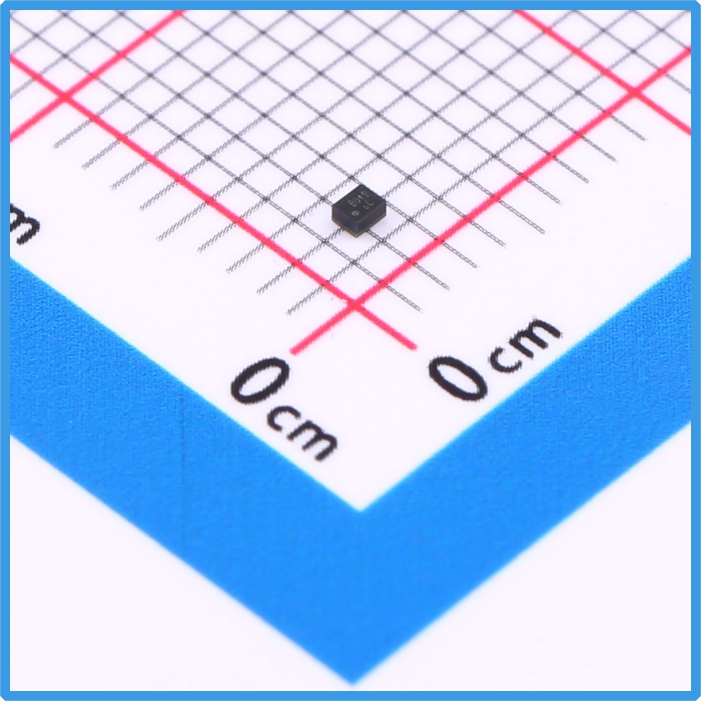
『Product Highlight』Kinghelm RF SAW Filter KH-SAWF158A
2026-05-29
68
With the rapid growth of smart vehicles, drones, wearable electronics, industrial IoT, and intelligent navigation devices, high-precision positioning technology has become an essential function in modern electronic products. From automotive navigation and asset tracking to portable GPS terminals and smart logistics systems, Global Navigation Satellite Systems (GNSS) are now widely integrated into numerous applications. In these RF receiving systems, Surface Acoustic Wave (SAW) filters play a critical role in ensuring signal stability and positioning accuracy.
Kinghelm KH-SAWF158A Product Image
To meet the increasing demand for multi-system navigation compatibility, Kinghelm introduced the KH-SAWF158A SAW Filter, a compact and low-loss RF filter designed for GPS, COMPASS (BeiDou), and GLONASS applications. With excellent insertion loss performance, high out-of-band attenuation, and ultra-small packaging, the KH-SAWF158A provides a reliable RF filtering solution for modern GNSS devices.
Growing Demand for Multi-Mode GNSS RF Filters
In recent years, GNSS technology has evolved from single-system GPS positioning to multi-mode satellite navigation combining GPS, BeiDou, and GLONASS. Multi-system positioning significantly improves navigation accuracy, satellite acquisition speed, and signal stability, especially in urban environments, underground parking areas, and industrial scenarios where signal interference and multipath effects are common.
However, GNSS signals are extremely weak and highly susceptible to interference from LTE, Wi-Fi, Bluetooth, and other wireless communication systems. Without effective RF filtering, unwanted signals and noise can reduce receiver sensitivity and negatively impact positioning performance.
The KH-SAWF158A was specifically developed to address these challenges. By accurately filtering target GNSS frequency bands while suppressing unwanted RF interference, the device helps maintain stable and high-quality signal reception in complex wireless environments.
Compact Structure Designed for Modern Electronics
As electronic products continue to become smaller and more integrated, RF components must also support compact PCB designs. The KH-SAWF158A adopts an ultra-miniature SMD-5P package with dimensions of only 1.1 × 0.9 mm, making it ideal for space-constrained applications such as wearable devices, navigation modules, and portable electronics.
The filter operates using Surface Acoustic Wave technology. Inside the device, interdigital transducers convert electrical RF signals into acoustic waves propagating along a piezoelectric substrate surface. Only the desired frequency signals are allowed to pass, while unwanted frequencies are attenuated, achieving precise frequency filtering.
Compared with traditional LC filter solutions, SAW filters offer several advantages, including:
Compact size
Excellent frequency selectivity
Stable high-frequency performance
High consistency in mass production
Lower design complexity
Because of these benefits, SAW filters are widely used in RF front-end circuits for wireless communication and satellite navigation systems.
The KH-SAWF158A features a center frequency of 1.5824 GHz and supports the operating bands required for GPS, BeiDou, and GLONASS systems.
Core Performance Advantages
The performance of an RF filter directly affects the sensitivity and reliability of GNSS receivers. The KH-SAWF158A is optimized for low insertion loss and strong out-of-band suppression to ensure stable navigation performance.
Low Insertion Loss
The filter provides only 2 dB insertion loss, minimizing signal attenuation in the RF receiving chain. Since satellite signals are naturally weak, reducing RF loss is critical for improving receiver sensitivity and satellite acquisition capability, particularly in weak-signal environments.
High Out-of-Band Attenuation
The KH-SAWF158A offers 40 dB attenuation performance, effectively suppressing interference from:
LTE communication signals
Wi-Fi signals
Bluetooth interference
Harmonic noise and RF spurious signals
This high rejection capability improves the signal-to-noise ratio of GNSS receivers and enhances overall positioning stability.
Multi-System GNSS Compatibility
The filter supports multiple navigation systems, including:
GPS
BeiDou (COMPASS)
GLONASS
Multi-mode GNSS positioning provides faster satellite tracking, improved positioning precision, and stronger anti-interference capability compared with single-system solutions.
Standard 50Ω Impedance Matching
The device adopts a 50-ohm input and output impedance design, allowing easy integration with mainstream RF front-end circuits and reducing matching complexity during system development.
Wide Range of Applications
Thanks to its compact size and reliable RF performance, the KH-SAWF158A can be widely used in various GNSS-enabled devices.
Automotive Navigation Systems
Modern vehicles require stable and accurate positioning performance even in dense urban environments. The KH-SAWF158A helps improve GNSS signal quality and navigation reliability in automotive applications.
Drones and UAVs
Drones rely heavily on accurate positioning for flight stability and route control. The low insertion loss design enhances weak-signal reception and supports stable navigation during flight.
Smart Wearable Devices
Wearable electronics demand highly integrated and compact components. The miniature SMD package of the KH-SAWF158A helps reduce PCB space usage while maintaining reliable GNSS performance.
Industrial IoT and Tracking Systems
The filter is also suitable for:
Asset tracking devices
Smart logistics terminals
Shared mobility systems
Portable navigation equipment
Industrial positioning modules
Surveying and mapping instruments
As the adoption of BeiDou and multi-mode GNSS technology continues to expand, the demand for high-performance RF filters will continue to grow across global markets.
Future Trends in RF Components
Driven by the rapid growth of 5G communication, smart vehicles, IoT devices, and satellite navigation technologies, the RF component industry is experiencing continuous innovation. SAW filters remain one of the most important components in RF front-end systems due to their compact size and stable filtering performance.
With the accelerating commercialization of BeiDou navigation systems, the demand for localized high-performance GNSS RF components is also increasing. Kinghelm continues to expand its product portfolio in RF connectors, antennas, and filtering solutions, providing reliable electronic components for wireless communication and navigation industries.
The KH-SAWF158A demonstrates Kinghelm’s capability in RF component development and offers customers a competitive solution for modern GNSS applications.
Kinghelm KH-SAWF158A Specification
Conclusion
As multi-mode satellite navigation becomes increasingly important in modern electronic systems, RF front-end performance plays a critical role in positioning accuracy and signal stability. The Kinghelm KH-SAWF158A SAW Filter combines low insertion loss, high attenuation performance, compact packaging, and multi-system compatibility to provide an efficient RF filtering solution for GPS, BeiDou, and GLONASS applications.
With the continued expansion of smart transportation, industrial IoT, drones, and wearable electronics, high-performance GNSS RF filters like the KH-SAWF158A will continue to support the development of more reliable and accurate positioning systems worldwide.
About Kinghelm
Shenzhen Kinghelm Electronics Co., Ltd.(www.kinghelm.net)has technical backbones from Tsinghua University and UESTC, and has introduced overseas returnee professionals. Kinghelm is able to develop highly reliable and high-performance antenna and connector products.KH series products of "Kinghelm" brand include Beidou/GPS antennas, RF adapter connectors, plug connector, electrical data connectors, terminals, and customized vehicle harnesses, industrial / medical connectors, and special antenna connectors."Kinghelm connects world", Kinghelm has grown with the development of China's Beidou industry. Starting from supplying Beidou/GPS dual mode antennas, IPEX terminals, and RF adapter cables for automotive manufacturers, Kinghelm has continuously developed products. Currently, it has a series of WiFi, Bluetooth, NB-loT, LoRa, Zigbee, UWB, and GSM antennas, RFID tags, RF adapter cables, standard microwave antennas, vehicle grade SMA, SMB, FAKRA holders, coaxial cables, and can customize non-standard antenna connectors based on customer drawings or samples.
KH-SAWF158AView Product Details

What is the significance of signal integrity testing for connectors?
2026-05-27
82
Signal integrity testing plays a critical role in evaluating the performance and reliability of connectors used in high-speed electronic systems. As transmission speeds continue to increase in applications such as 5G communication, automotive electronics, industrial automation, servers, medical equipment, and consumer electronics, connectors are required to handle large volumes of data with minimal signal loss or interference. Signal integrity testing ensures that connectors can maintain stable electrical performance under these demanding conditions.
The primary significance of signal integrity testing is to verify whether a connector can accurately transmit signals without introducing excessive distortion, attenuation, reflection, delay, or electromagnetic interference. During high-speed data transmission, even small impedance mismatches or structural inconsistencies inside a connector may cause signal reflections, crosstalk, insertion loss, or return loss. These issues can reduce transmission quality, create data errors, or even lead to complete system failure.
Signal integrity testing helps engineers identify these problems during the product design and validation stages. Common test parameters include insertion loss, return loss, crosstalk, impedance matching, eye diagram analysis, and propagation delay. By analyzing these indicators, manufacturers can optimize connector structures, terminal layouts, shielding designs, and material selection to improve overall transmission efficiency and reliability.
In high-frequency environments, connectors are often exposed to electromagnetic interference (EMI). Signal integrity testing also evaluates the shielding effectiveness and anti-interference capability of connectors, ensuring stable communication even in electrically noisy environments. This is especially important for automotive radar systems, industrial control equipment, and high-speed networking devices where signal accuracy directly affects operational safety and performance.
Another important significance of signal integrity testing is compatibility with international standards and industry requirements. Many industries require connectors to comply with standards such as USB, HDMI, PCIe, Ethernet, or automotive specifications. Comprehensive signal integrity testing helps manufacturers verify compliance and improve product competitiveness in the global market.
In addition, signal integrity testing contributes to long-term product reliability. Connectors may experience temperature changes, vibration, humidity, and repeated mating cycles during operation. Testing can reveal how these environmental factors influence signal performance over time, allowing engineers to enhance durability and maintain stable signal transmission throughout the connector’s service life.
Overall, signal integrity testing is essential for ensuring connector performance, improving system stability, reducing transmission errors, and supporting the development of modern high-speed electronic devices. It provides a scientific basis for connector optimization and guarantees reliable signal transmission in increasingly complex electronic applications.

How can severe crosstalk in multi-channel connectors be optimized?
2026-05-27
86
I. Design-level optimization
Increase channel spacing: Keep spacing between adjacent signal terminals or cables at ≥ 1/10 of the signal wavelength, or follow the values recommended in the connector datasheet.
Optimize terminal arrangement: Use a "signal–ground–signal" interleaved layout, with ground terminals blocking electromagnetic coupling.
Enhance shielding design: Add independent shielding for critical channels or use fully shielded connector housings, ensuring the shield is reliably grounded.
Use differential signaling: Design sensitive signals as differential pairs to utilize their common-mode noise rejection to cancel crosstalk.
II. Selection and replacement adjustments
Switch to low-crosstalk connectors: Prioritize high-speed connectors with precise impedance matching and robust shielding (such as high-speed backplane or differential connectors).
Reduce channel density: If channels are too dense, split signals across multiple lower-density connectors.
Select high-quality insulating materials: Use materials with stable dielectric constants to reduce dielectric coupling interference.
III. Usage and routing guidelines
Standardized routing: Avoid dense parallel routing of breakout cables. Separate critical and general signal cables, and keep spacing ≥ 3 times the cable diameter.
Reliable grounding: Ground shields and ground terminals using single-point or multi-point grounding to form an equipotential plane.
Reduce frequency or data rate: When application conditions allow, slightly lowering signal frequency or data rate can reduce electromagnetic radiation and crosstalk.

Pin Header Connector: Types, Sizes, and How to Choose the Right One for Your PCB
2026-05-26
149
What Is a Pin Header Connector? (Quick Answer)
A pin header connector is a low-profile electrical connector consisting of an array of metal pins held in a plastic housing, used to create removable or semi-permanent electrical connections on a PCB. It is one of the most widely used connector families in electronics—from hobby Arduino projects to industrial control boards.
Who this guide is for: Electronics engineers, PCB designers, and technical buyers who need to select the correct pin header type, pitch, and mounting style for a specific application.
Who should look elsewhere: If you need high-current (>5 A per pin), high-frequency RF, or ruggedized mil-spec connections, dedicated connector families (such as automotive or coaxial connectors) are better starting points.
Why Pin Header Connectors Are a PCB Design Staple
Pin header connectors solve a fundamental problem in electronics: how do you create a reliable, re-mateable electrical interface without soldering wires directly to a board?
Their advantages are well-established:
Modularity— boards can be stacked, swapped, or tested independently.
Low cost— standard pitch versions are among the least expensive connectors per circuit.
Design flexibility— available in virtually any pin count, row configuration, and mounting style.
Toolless mating— the female socket (pin header socket / pin header female) slides onto the male header without tools.
These properties explain why pin header PCB layouts appear in development boards, sensor modules, power management cards, and communication peripherals across virtually every electronics segment.
Pin Header Types: A Practical Overview
Understanding pin header types prevents the most common design errors. The primary classification axes are row count, orientation, and mounting method.
Single-Row vs. Double-Row
Single-row headerscarry one line of pins. They are compact and common for simple I/O breakouts.
Double-row (dual-row) headerscarry two parallel lines, doubling density for the same board footprint. Widely used in JTAG, ISP programming, and inter-board connectors.
Triple-row and higherexist but are less standard; verify socket availability before committing to a non-standard row count.
Straight (Vertical) vs. Right-Angle
Straight headersmount perpendicular to the PCB surface. They are the default choice when mating connectors approach from above the board.
Right-angle headersexit parallel to the PCB surface—useful when connectors must mate at a panel edge or when vertical clearance is constrained.
Through-Hole vs. SMD Pin Header
Through-hole pin headerspass through the PCB and are soldered on the opposite side. They offer superior mechanical retention and are the standard for most prototyping and mid-volume production.
SMD pin header(surface-mount) variants sit on one side of the board with gull-wing or J-bend leads. They eliminate drill costs and work well in high-density designs where automated pick-and-place is the assembly method. Verify your reflow profile against the housing material rating before use—most standard housings are rated for one reflow cycle at ≤260 °C per IPC/JEDEC J-STD-020.
Pin Header Sizes and Dimensions: The Numbers That Matter
Pin header sizes are primarily defined by pitch (center-to-center pin spacing), pin diameter, pin height, and insulator body dimensions.Pitch: The Most Critical Dimension
Pitch
Common Application
1.00 mm
Ultra-compact IoT and wearable designs
2.54 mm (0.1 in)
Most common; breadboard-compatible; general prototyping and production
2.00 mm
Compact consumer electronics, laptops
1.27 mm
High-density boards, small modules
The 2.54 mm pin header remains the industry default. Its 0.1-inch spacing is directly compatible with standard breadboards and a vast ecosystem of cables, sockets, and shields. If your design has no compelling reason to deviate, 2.54 mm pitch reduces sourcing risk and assembly error rates.
Pin Header Dimensions Beyond Pitch
Pin diameter:Typically 0.64 mm square (for 2.54 mm pitch). This must match the socket contact opening.
Insulator height (above PCB):Standard is approximately 2.54 mm for the base; total mated height varies by pin length (short: ~3 mm exposed; standard: ~6 mm; long: ~11 mm).
Pin count:1×2 up to 1×40 for single-row; 2×2 up to 2×40 for dual-row are the most commonly stocked configurations.
How to verify dimensions: Cross-reference the manufacturer's datasheet against IPC-7251 land pattern standards. Most EDA tools (KiCad, Altium) include verified footprint libraries—audit the courtyard and copper pad dimensions against your chosen part's drawing before sending to fabrication.
Pin Header Male vs. Pin Header Female: Mating Pair Basics
The terms pin header male and pin header female (also called pin header socket) describe the two halves of a mating pair.
Pin header male:The housing holds rigid pins that protrude upward (or outward). This is the component soldered to the PCB.
Pin header female / pin header socket:A housing with internal spring contacts that receive the male pins. The female half may be soldered to a second PCB (for board-to-board stacking), crimped to wire ends (for wire-to-board connections), or used in an IDC (insulation-displacement) ribbon cable assembly.
Key selection rule: The female contact's retention force must be specified and matched to the expected mating cycles. Standard pin header sockets are typically rated for 30–100 insertion/withdrawal cycles. If your application requires frequent disconnection (field-serviceable modules, test fixtures), verify the mating cycle rating in the datasheet and consider a higher-cycle-rated variant.
How to Select the Right Pin Header for Your PCB Design
A structured selection process avoids the most costly redesign scenarios.
Step 1 — Define the Electrical Requirements
Maximum current per pin (derate by 50% from rated value for thermal margin in enclosed enclosures)
Voltage: most standard pin headers are rated 250 V AC max, but verify for your specific series
Signal type: low-speed digital, high-speed differential, or power-only
Step 2 — Choose Pitch Based on Density and Ecosystem
Default to 2.54 mm unless density constraints force a smaller pitch. Smaller pitches require finer PCB tolerances and more precise assembly—cost and yield implications should be evaluated early.
Step 3 — Select Mounting Style
Use through-holewhen mechanical strength matters (connector is frequently mated/unmated, subject to vibration, or hand-assembled).
Use SMD pin headerwhen board thickness is constrained, drill costs are significant, or full SMT assembly is required for process consistency.
Step 4 — Confirm Pin Count and Row Configuration
Single-row headers are simpler to route; dual-row headers are more compact but require careful via and trace planning in the breakout region. For programming headers (JTAG, SWD, ISP), follow the reference pinout defined by the microcontroller vendor to maintain cable compatibility.
Step 5 — Verify the Mating Socket Availability
A male header is useless without a compatible female socket. Confirm that the pin header socket for your chosen pitch, row count, and pin count is available from multiple sources before finalizing the design. Single-source availability is a supply chain risk.
Step 6 — Review Thermal and Environmental Ratings
Standard housings are typically PA66 (nylon) or LCP. PA66 is adequate for most applications; LCP offers better dimensional stability at elevated temperatures and during SMT reflow. Check the operating temperature range against your application environment.

What are the consequences of a connector short circuit?
2026-05-26
76
A connector short circuit occurs when unintended electrical contact is formed between conductive parts, such as adjacent terminals, signal lines, or power and ground connections. This abnormal connection allows excessive current to flow through the circuit, which can seriously affect the performance, reliability, and safety of electronic systems. The consequences of a connector short circuit can range from minor functional issues to severe equipment damage and safety hazards.
In mild cases, a connector short circuit may cause temporary circuit abnormalities, unstable signals, communication errors, or intermittent device malfunction. Sensitive electronic components such as integrated circuits, sensors, and microcontrollers may become damaged due to excessive current or voltage fluctuations. In some situations, overheating caused by the short circuit can burn connector contacts, melt insulation materials, or deform terminals, reducing connector reliability and service life.
In more serious cases, a connector short circuit can lead to power supply failures, system shutdowns, or complete equipment breakdown. High current generated during a short circuit may damage printed circuit boards, wiring harnesses, batteries, or power modules. In industrial automation, automotive electronics, and energy storage systems, severe short circuits can trigger cascading failures across multiple connected circuits or devices.
Safety risks are also a major concern. Excessive heat generated by a connector short circuit may cause smoke, sparks, or even fire hazards, especially in high-power applications. In battery-powered systems, a short circuit can result in thermal runaway, which may lead to explosions or serious safety incidents. For this reason, many electronic systems include protective components such as fuses, circuit breakers, overcurrent protection devices, and insulation barriers to reduce the risk of damage caused by short circuits.
Common causes of connector short circuits include improper installation, damaged insulation, contamination by dust or moisture, metal debris, poor connector design, excessive vibration, and mechanical wear. Regular inspection, proper connector selection, reliable insulation design, and correct assembly procedures are essential for preventing short circuits and ensuring stable system operation.
Overall, connector short circuits can have cascading consequences that affect both equipment performance and user safety. Preventive design and maintenance are critical in modern electronic and electrical systems.
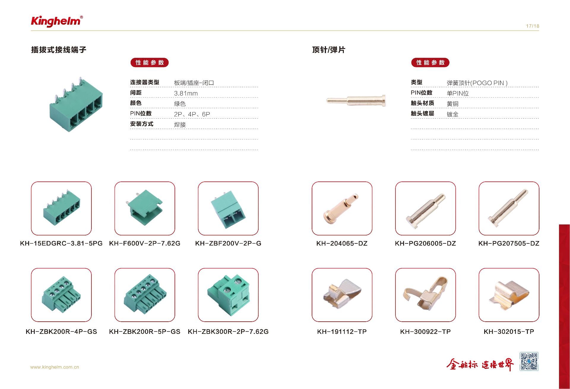
Is connector impedance fixed?
2026-05-26
76
No, connector impedance is not fixed. The impedance of a connector can vary depending on several electrical, structural, and environmental factors. In high-speed signal transmission systems, connector impedance plays a critical role in maintaining signal integrity, reducing reflections, and ensuring stable data communication. Because impedance changes with operating conditions and connector design, engineers must carefully optimize connector structures for controlled impedance applications.
One of the key factors affecting connector impedance is the signal-to-ground ratio. In many high-speed connector designs, a 1:1 signal-to-ground ratio is considered ideal because it helps maintain stable electromagnetic fields and minimizes signal interference. If the arrangement of signal pins and ground pins changes, the impedance profile of the connector will also change, potentially leading to signal reflections or transmission losses.
Signal frequency is another major influencing factor. At low frequencies, impedance variation is relatively small. However, at high frequencies, parasitic inductance and capacitance become more significant, causing impedance to fluctuate more noticeably. This is especially important in applications such as USB, HDMI, PCIe, automotive communication systems, and RF connectors, where maintaining controlled impedance is essential for high-speed data transmission.
The physical structure and materials used in the connector also directly affect impedance stability. Factors such as terminal spacing, contact geometry, shielding design, conductor dimensions, and the dielectric constant of insulating materials all influence the connector’s characteristic impedance. Even small manufacturing tolerances can create impedance discontinuities that impact signal performance.
In practical electronic design, connectors are often engineered to match standard impedance values such as 50 ohms, 75 ohms, 90 ohms, or 100 ohms depending on the application. Maintaining impedance consistency across cables, connectors, and printed circuit boards helps reduce signal distortion and improve overall system reliability.
Therefore, connector impedance should be viewed as a controlled parameter rather than a completely fixed value. Proper connector selection and optimized PCB layout are essential for achieving stable high-speed signal transmission and reliable electronic performance.
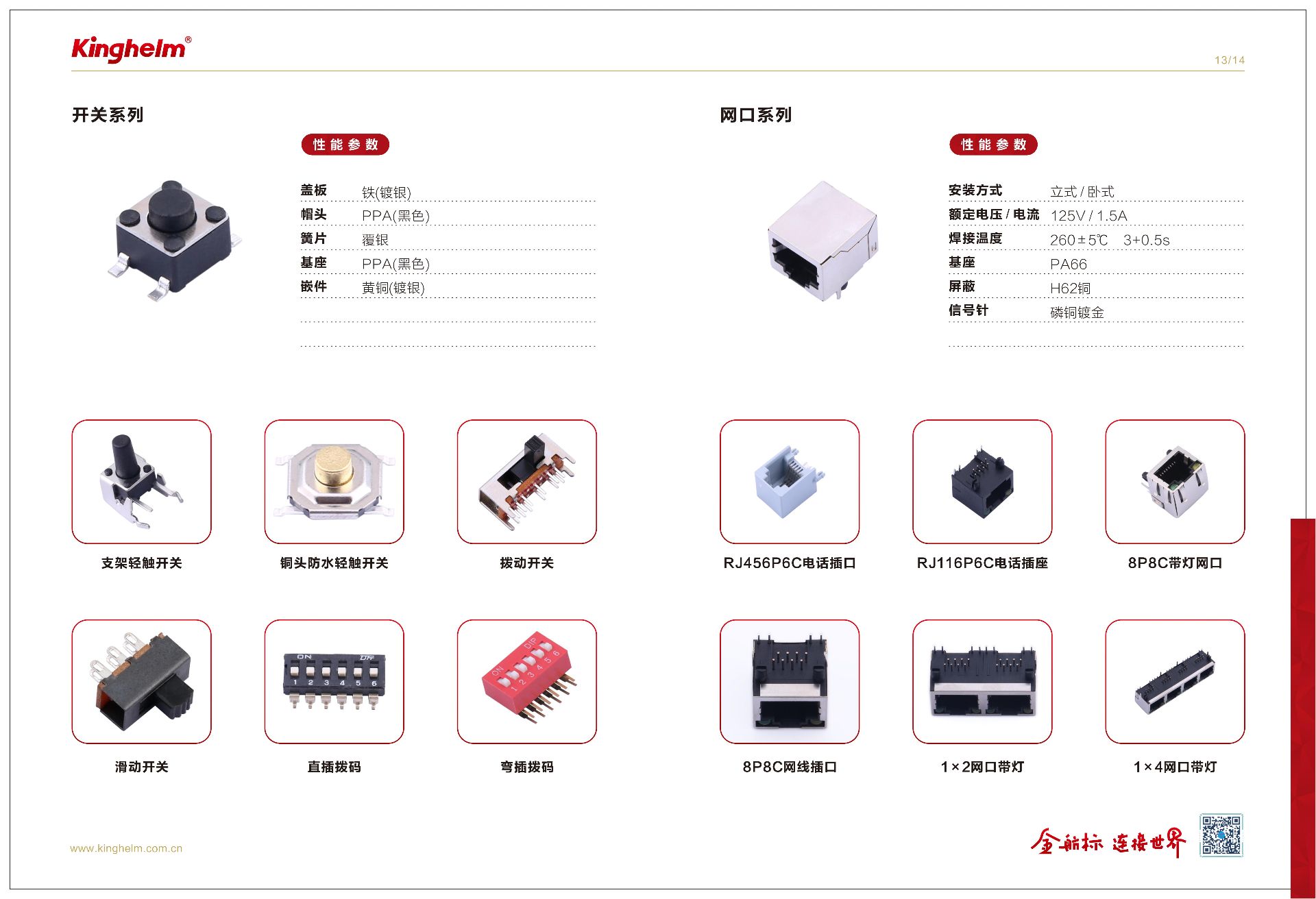
What does the current rating of a connector mean?
2026-05-26
110
The current rating of a connector refers to the maximum amount of electrical current that the connector can safely carry continuously under specified operating conditions without causing excessive temperature rise, performance degradation, or damage to the connector and surrounding equipment. It is also commonly called the rated current. Current rating is one of the most important electrical parameters when selecting connectors for electronic devices, industrial equipment, automotive systems, and communication applications.
The current rating of a connector is determined by several factors, including the contact material, contact resistance, terminal size, plating quality, insulation material, ambient temperature, wire size, and cooling conditions. When electrical current flows through the connector contacts, heat is generated due to electrical resistance. If the current exceeds the rated value, the connector may overheat, leading to insulation aging, contact deformation, reduced conductivity, or even failure of the electrical system.
Different connectors are designed for different current capacities. Small signal connectors may only support currents below 1A, while power connectors used in industrial or automotive applications can handle tens or even hundreds of amperes. Manufacturers usually specify the current rating based on standardized testing conditions, such as a certain ambient temperature and wire gauge. Therefore, engineers should carefully review datasheets and consider real-world operating environments when selecting connectors.
In practical applications, choosing a connector with an appropriate current rating helps improve system reliability, safety, and long-term performance. A connector operating below its maximum rated current generally provides better thermal stability and longer service life. For high-current applications, designers may also use multiple contacts in parallel or select connectors with enhanced heat dissipation capabilities.
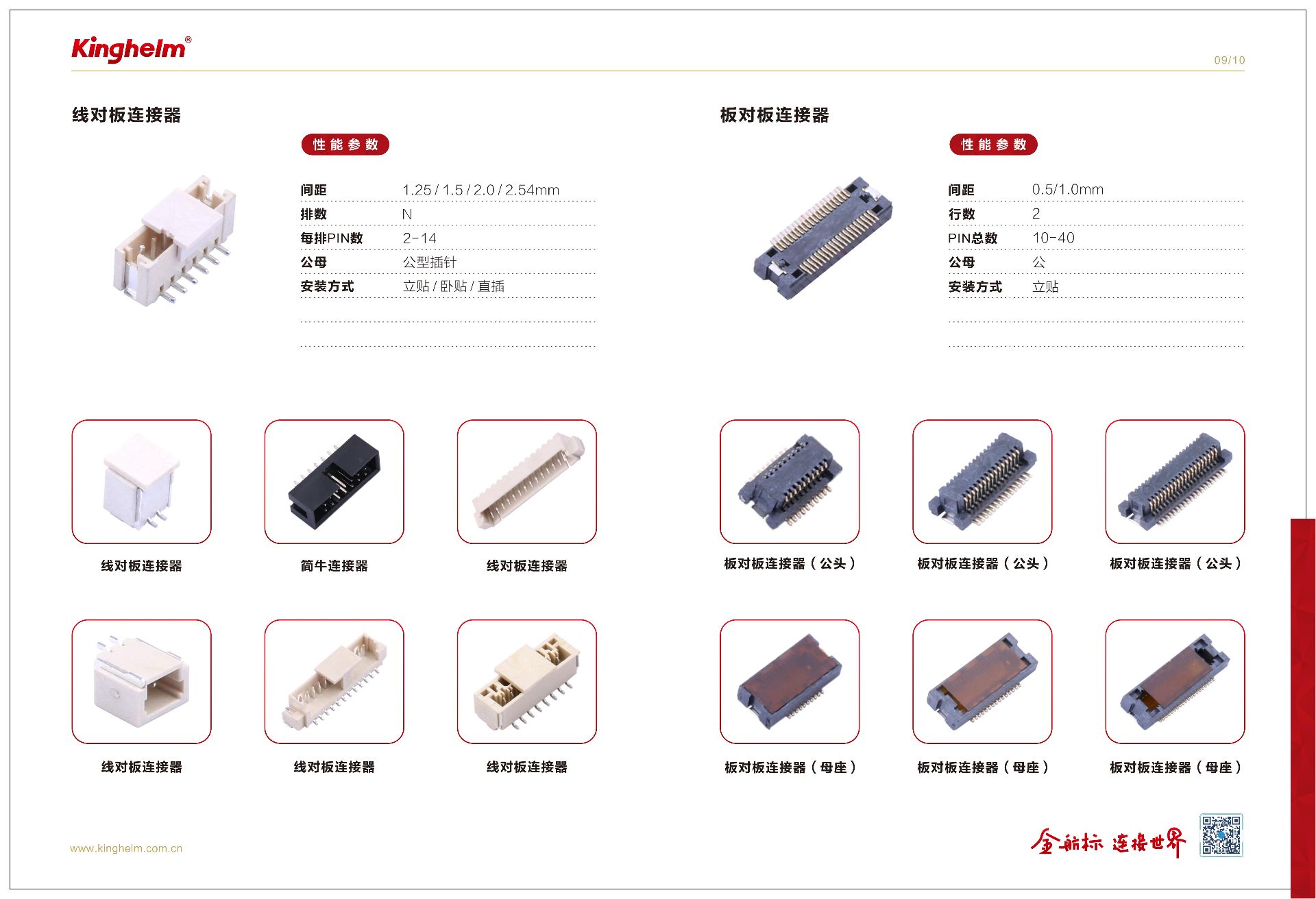
Why Are Foolproof (Keying) Designs Used in Connectors?
2026-05-25
104
Foolproof, or keying, designs are widely used in connectors to prevent incorrect insertion, reverse mating, or mismatched connections during installation and operation. In modern electronic and electrical systems, connectors often carry power, high-speed signals, or sensitive data. If a connector is inserted incorrectly, it may lead to short circuits, signal transmission errors, equipment malfunction, or even permanent damage to electronic components. Keying structures are therefore essential for ensuring safe, reliable, and accurate connections.
A keying design works by adding specific physical features to the connector interface, such as asymmetrical shapes, slots, ribs, grooves, guide pins, or uniquely positioned contacts. These features allow the connector to mate only in the correct orientation and with the correct counterpart. If the user attempts to insert the connector incorrectly, the physical structure blocks the connection, preventing operational mistakes before electrical contact occurs.
In industrial automation, automotive electronics, medical devices, communication equipment, and consumer electronics, foolproof connector designs greatly improve installation efficiency and reduce human error. Technicians and assembly workers can quickly identify the correct orientation without relying heavily on labels or manuals, which is especially important in high-density systems with multiple similar connectors.
Keying designs also enhance maintenance and replacement processes. During repairs or upgrades, connectors can be disconnected and reconnected safely without risking reversed polarity or incorrect port matching. This reduces downtime and improves overall system reliability.
Additionally, foolproof designs help manufacturers improve production quality and consistency in automated assembly environments. Automated equipment can align and connect components more accurately, reducing assembly defects and improving manufacturing efficiency.
As electronic systems become smaller, faster, and more complex, the importance of reliable connector keying continues to increase. Proper foolproof connector design not only protects devices and circuits but also supports long-term operational stability and user safety.
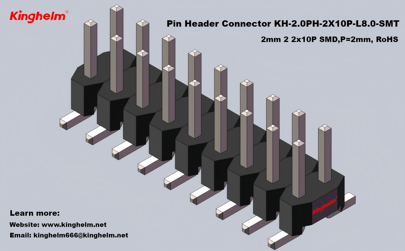
What advantages do connectors have compared with soldering?
2026-05-25
127
Compared with soldering, connectors offer key advantages in removability, maintainability, and mass production, while providing flexibility and safety:
Easy installation and maintenance: No specialized tools are required, enabling quick mating and replacement of components or system upgrades without heat damage caused by soldering.
Strong suitability for mass production: Standardized designs support automated assembly, significantly improving efficiency and consistency compared with manual soldering.
High application flexibility: The same interface can be used with different components, allowing easy configuration, expansion, or modification, unlike permanent soldered connections.
Protection of critical components: No high-temperature processes are involved, reducing the risk of damage to sensitive chips, cables, and substrates.
Improved operational safety: Eliminates the need for specialized soldering skills and reduces defects such as cold joints or missed soldering, as well as high-temperature hazards.

Do higher signal transmission frequencies place lower requirements on connectors?
2026-05-25
100
Higher signal transmission frequencies place higher requirements on connectors. At high frequencies, signal attenuation, distortion, and crosstalk become more significant, requiring stricter design controls to ensure signal integrity.
High-frequency signals are more susceptible to loss and distortion, so connectors must optimize impedance matching (e.g., tightly controlling 50 Ω or 100 Ω characteristic impedance) to reduce reflection loss.
Electromagnetic coupling is stronger at high frequencies, requiring enhanced shielding (such as metal shells and shielding partitions) and optimized pin layouts to minimize crosstalk.
High-frequency applications also demand higher material quality and manufacturing precision, including low-loss insulating materials (e.g., PTFE), high-precision contacts, and tight dimensional tolerances to prevent signal leakage.