Service Hotline
News

News
Struggling with Bluetooth Antenna PCB Footprint Design? Here's How to Optimize It Step by Step
2025-08-05
1289
In Bluetooth hardware design, the PCB footprint is the “invisible cornerstone” that determines antenna performance. Even with the same Bluetooth module, poor PCB footprint design—such as a 0.2 mm pad misalignment or missing ground plane—can cause signal strength to plummet from -55 dBm to -85 dBm, reducing transmission range by over 60%. This article systematically explains the core design factors, common types, and practical techniques for Bluetooth antenna PCB footprints, helping hardware engineers avoid 90% of design pitfalls.
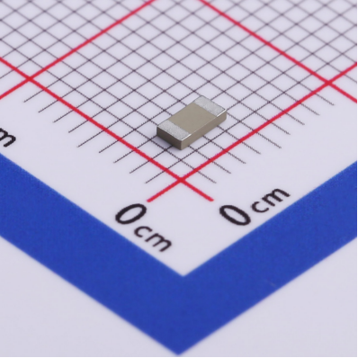
I. Four Core Parameters of Bluetooth Antenna PCB Footprint (Critical to Performance)
1. Physical Dimensions: Precise Matching to Wavelength
Bluetooth operates in the 2.4 GHz band (λ ≈ 12.5 cm), and antenna dimensions must be proportionate to the wavelength:
Monopole antennas: Length ≈ λ/4 (≈3.1 cm); width adjusted for impedance (typically 1–3 mm)
Inverted-F antennas (PIFA): Total height ≈ λ/8 (~1.5 cm), radiator arm ≈ λ/4 (tolerance ≤0.5 mm to prevent ±20 MHz frequency shift)
Chip antennas: Side length ≈ λ / (2√εr) (εr = dielectric constant; e.g., FR4 εr = 4.4 → ~1.8 cm)
Design note: A 0.1 mm size deviation can shift center frequency by 5–8 MHz. Calibration via simulation tools like HFSS is recommended.
2. Pad and Feedline Design: The “First Gateway” of Signal Flow
Pad Parameters:
Feed pad diameter: 0.8–1.2 mm (fits 0.3 mm solder wire); spacing to RF output pad ≤0.5 mm to minimize parasitic inductance
Ground pad area ≥5× the feed pad (e.g., 1 mm2 feed pad → ≥5 mm2 ground pad) to ensure ground resistance <0.05Ω
Feedline Design:
Use 50Ω microstrip (on FR4: width ≈ 0.9 mm); length ≤5 mm (every extra 1 mm = ~0.1 dB signal loss)
Avoid sharp corners (use 45° or curved traces); right-angle bends may introduce impedance mismatch up to 10Ω
3. Ground Plane Layout: The “Stabilizer” of Radiation
Keep ideal ground-plane spacing relative to the antenna:
Chip antenna: Edge of ground plane ≥3 mm from radiator edge (prevents edge-field interference)
PIFA: Ground plane beneath antenna should be ≥2× antenna area (e.g., 10×10 mm antenna → ≥20×20 mm ground)
Ground plane integrity:
Avoid cutouts or high-speed signals (e.g., USB traces) under the antenna, as these disrupt ground continuity and can raise VSWR from 1.2 to 2.5.
4. Substrate selection: The “Hidden Variable” in Footprint Performance
FR4: Low-cost (~$1.50/board), suitable for consumer devices (e.g., Bluetooth speakers); needs margin in layout due to dielectric variation (±2% with temperature)
Ceramic: High εr (20–90), enabling 40% smaller footprints; brittle, suitable for precision devices (e.g., medical sensors), with 0.5 mm edge clearance recommended
FPC substrates (e.g., LCP): εr ≈ 3.0; flexible, bendable (min. bend radius ~1 mm), ideal for wearables; use ≥1 oz copper for robust feedline
II. 3 Common Bluetooth Antenna PCB Footprint Types & Applications
1. Chip-Type Footprint (Most Versatile, for Compact Devices)
Structure: Rectangular copper radiator (e.g., 15×10 mm), edge-fed, ground layer underneath
Performance: Gain 0–2 dBi, bandwidth ≥80 MHz (covers 2.4–2.48 GHz), suitable for BLE devices (e.g., fitness bands)
Design Tip: Add 0.2 mm “tuning stubs” to radiator edges; trimming 0.1 mm raises frequency ~3 MHz
2. Inverted-F (PIFA) Footprint (High Integration, Ideal for Metal-Enclosure Devices)
Structure: Radiator arm (λ/4) + shorting pin to ground + feedline; total height ≤5 mm (good for slim devices)
Advantages: Less affected by metal housing (30% better anti-interference than chip antenna); suited for earbuds, smartwatches
Critical Dimension: Distance between feed and shorting pin: 2–3 mm (affects impedance; every 0.1 mm increase = +2Ω)
3. Monopole Footprint (For Long-Range, Open Environments)
Structure: Slender radiator (λ/4), grounded at base, simple layout with no complex ground plane
Performance: Gain 1–3 dBi; 20% longer range than chip antenna in same environment; ideal for Bluetooth gateways
Layout Tip: Keep a 20 mm metal-free zone around radiator (to prevent distorted radiation pattern; up to -15 dB in affected directions)
III. 5-Step PCB Footprint Design Process (with Simulation Validation)
1. Requirement Definition & Parameter Planning
Identify Bluetooth type: Classic Bluetooth (requires EDR and wider bandwidth) vs BLE (low power, narrower bandwidth)
Set performance goals: e.g., RSSI ≥ -75 dBm at 10 meters, VSWR ≤ 1.5, bandwidth ≥85 MHz
Choose substrate: Based on thickness (<3 mm → ceramic) and cost (mass production → FR4)
2. Initial Layout Design
Use Altium Designer or KiCad for footprint drawing:
Radiator dimensions via λ/4 formula (accounting for εr)
Feedline width for 50Ω (e.g., FR4 with 1.6 mm thickness → ~1.2 mm line width)
Ground-to-radiator spacing ≥5 mm to reduce coupling
3. Simulation Optimization (Key to Reducing 80% of Trial-and-Error)
Import model into simulation tools (e.g., CST, ADS), test:
Return Loss (S11): ≤ -10 dB across 2.4–2.485 GHz
Radiation Pattern: For omnidirectional antennas, horizontal gain variation ≤3 dB
Impedance: 50Ω ±5Ω; outside range → adjust feedline width or add matching caps
4. Prototyping & Testing
Create 3–5 test boards with slight tuning variations (e.g., radiator ±0.3 mm)
Measure S-parameters with network analyzer:
Center frequency offset >10 MHz → trim radiator (long → shorten; short → extend)
Impedance mismatch (e.g., 65Ω) → add 1pF capacitor in series (reduces ~10Ω)
5. Mass Production Adjustment
Validate dielectric variation between FR4 batches (±0.2 in εr); reserve 0.5 mm tuning margin
Adjust solder mask design:
No solder mask over radiator surface (to reduce εr variation)
Open window on pad area (for better solderability)
IV. Common Footprint Issues & Solutions (With Cases)
Issue | Root Cause | Solution |
Center frequency shift (e.g., 2.42 → 2.46 GHz) | Radiator too short (e.g., designed 31 mm → actual 30.5 mm) | Extend radiator by 0.5 mm (every +0.1 mm lowers frequency ~5 MHz) |
Impedance too high (e.g., 60Ω) | Feedline too narrow (designed 0.8 mm → made 0.6 mm) | Widen to 1.0 mm (each +0.1 mm width reduces ~3Ω) |
Distorted radiation pattern | Ground plane too small (<2× radiator) | Expand ground to 3× radiator area; round corners |
Poor batch consistency | Dielectric constant fluctuations | Use high-stability substrate (e.g., ceramic) or add compensation circuits |
Conclusion: The “Golden Rule” of Footprint Design
The essence of Bluetooth antenna PCB footprint design lies in precise sizing, impedance matching, and proper grounding. Always consider Bluetooth type (Classic/BLE), device form factor (metal/plastic housing), and substrate properties. Use simulations to reduce trial cost. Remember: a 0.1 mm dimension error can cause a 10 dB signal difference, while a well-designed ground plane can improve radiation efficiency by over 40%.
Need a custom footprint design for specific devices (e.g., TWS earbuds, IoT sensors)? Provide your 3D model and performance targets to receive a tailored PCB footprint solution—including layout files and simulation data.
Related Recommendations