Service Hotline
News

News
Medical Device Connectivity: Why Wire-to-Board Connectors Matter
2025-08-19
390
In connected healthcare, every signal must cross from cable to PCB without drift, noise, or interruption. That simple hand-off depends on the wire to board connector, a compact interface that governs power integrity, data fidelity, and serviceability. For procurement and engineering teams in consumer electronics companies now building patient-adjacent products, the choice of a wire to board connector is no longer routine; it is a strategic control point for compliance, warranty exposure, and brand equity. selecting well improves assembly yield, streamlines validation, and prevents costly field returns. Choosing poorly injects variability where a medical workflow can least afford it.
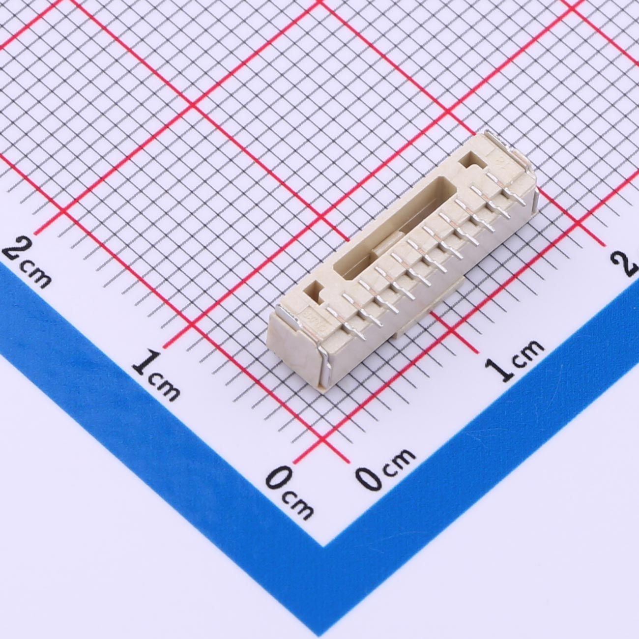
Defining the role of the wire to board connector in medical device connectivity
Although compact, the wire to board connector serves as a mechanical anchor, an electrical gateway, and a service interface. It must secure conductors against vibration and shock, maintain low contact resistance under thermal cycling, and tolerate cleaning agents common to clinical spaces. Beyond raw continuity, it influences EMC behavior, creepage/clearance geometry, and touch-safe design. Procurement teams care because footprint, plating, and housing polymer choices shape cost and supply resilience. Engineering groups care because pin pitch, polarization, and retention style determine assembly escapes and field reliability. In short, the interface decides whether a sophisticated subsystem behaves predictably through real-world handling.
Why procurement and engineering should align around the wire to board connector
Cross-functional alignment reduces life-cycle risk. Commodity thinking often underestimates how a wire to board connector drives conformance to IEC 60601 creepage, ingress protection, and insulation coordination targets. A disciplined sourcing plan balances availability, second-source viability, and change-notification rigor. Meanwhile, engineering owns fit, form, and function decisions that shape harness routing, strain relief, and board layout. When teams synchronize on current rating, plating thickness, and locking mechanism, builds stabilize earlier, procurement avoids last-minute alternates, and validation closes faster. That coordination turns a modest part into a program-level risk reducer.
Technical parameters that truly matter for a wire to board connector
Specification sheets can overwhelm. Focus on parameters that move outcomes: contact geometry, spring force, base metal, plating, pitch, current density, temperature rise, and retention. A robust wire to board connector manages micro-motion through wiping action and defined normal force, keeps resistance stable across humidity swings, and resists fretting corrosion. Housing polymer and latch design protect against mated-pair loosening during drop or transport. Cable exit style and crimp barrel geometry influence strain relief. Each element rolls up to fewer intermittent faults and tighter measurement stability.
Contact system and base materials
Contacts built on high-spring alloys (for example, phosphor bronze or beryllium copper) store elastic energy that preserves mating force after cycles. Nickel underplates block diffusion. Precious metal finishes (gold over nickel) limit oxide growth at low signal levels. When mating cycles rise, thicker deposits sustain performance. A quality wire to board connector matches finish to environment rather than relying on cosmetic sheen.
Plating thickness and finish strategy
Gold thickness around the contact interface should reflect expected cycles, humidity, and current density. selective plating controls cost while protecting wear areas. For power pins, tin over nickel may be adequate; for microvolt sensing, hard gold mitigates micro-arcing. The right wire to board connector combines selective regions so the design pays for performance only where it matters.
Pitch, current rating, and temperature rise
Higher density shrinks boards but raises resistance and heat. Verify derating curves rather than headline amperage. Evaluate temperature rise at the harness level because multiple loaded circuits inside a small housing can compound heat. A conservative wire to board connector specification keeps margin for ambient swings and enclosure constraints.
Retention, polarization, and mis-mating defenses
Positive latches, friction ramps, and keyed shrouds prevent partial engagement. Polarization features block reversed insertion. CPA (connector position assurance) designs add a secondary lock after full mate. A medical-ready wire to board connector anticipates hurried maintenance and still protects the assembly from error.
Harness interface and strain relief
Crimp quality dominates reliability. Use validated applicators and pull-test targets. For small gauges, dual-crimp barrels stabilize conductor and insulation separately. Over-molding or heat-shrink with adhesive reduces flex concentration. The most durable wire to board connector integrates cable exit geometry that guides bend radius away from the contact tail.
Compliance, safety, and documentation expectations surrounding the wire to board connector
Medical programs live under documented controls. Component selection should reference IEC 60601 for basic safety and essential performance, ISO 14971 for risk management, and IEC 60601-1-2 for EMC. Quality systems aligned to the FDA Quality System Regulation support traceability and change control. A vetted wire to board connector simplifies risk files by offering test data for flammability, glow-wire, and biocompatibility as applicable. Vendors that provide material declarations, PPAP-like packages, and PCN policies reduce audit friction. Comprehensive documentation avoids rework when auditors scrutinize interface decisions.
Reliability by design: failure modes to prevent with a wire to board connector
Field issues concentrate around a few mechanisms: fretting corrosion, incomplete mating, latch fatigue, conductor pull-out, and thermal runaway under load. Each mechanism has a countermeasure. Proper plating and contact force suppress fretting. Clear tactile and audible feedback helps users confirm full insertion. Robust latch geometry resists creep at elevated temperature. Correct crimp height preserves gas-tight joints. Conservative derating avoids hot spots. A disciplined wire to board connector strategy bundles these controls so the interface remains stable despite transport shock and clinical handling.
Design for manufacturing and total cost of ownership with the wire to board connector
Piece price tells only part of the story. Assembly minutes, scrap, and rework dominate real spend. Choose a wire to board connector with features that speed alignment and prevent mis-insertions. Fiducials and chamfers guide operators; polarization reduces training time; CPA features cut NFF (“no fault found”) returns. Upfront investment in applicators or semi-automatic crimp tools lowers variability. Packaging formats—tape-and-reel or stick—modify placement rates. Over the product life, those details slash cost while lifting process capability.
Process controls that protect builds
Incoming inspection: gauge plating thickness, verify crimp barrel dimensions, and sample latch force.
Assembly validation: pull-test wires by gauge, log crimp height distributions, and record insertion force windows.
Environmental checks: cycle humidity and temperature to confirm contact resistance stability.
End-of-line assurance: use continuity and hipot routines with controlled ramp rates.
selection checklist for a medical-grade wire to board connector
Structured selection saves time and limits surprises. Use a checklist that captures electrical targets, mechanical constraints, and compliance needs. The following items keep teams aligned while screening candidates:
Rated current per circuit at defined ambient and allowable temperature rise.
Contact base metal, underplate, and surface finish thickness at the mating interface.
Pitch, pin count options, and available keying variants.
Latch style, CPA availability, and polarization geometry.
Operating temperature range and chemical resistance of housing polymer.
UL flammability rating and glow-wire performance where applicable.
EMC implications: shielding accessories, ground pins, and layout guidance.
Crimp terminal portfolio by wire gauge and insulation diameter.
Packaging for automated placement or manual harness build.
Supplier PCN policy, last-time-buy practices, and dual-source options.
Supplier evaluation: what distinguishes a dependable source of the wire to board connector
Not all vendors support regulated markets equally. Favor partners with published reliability data, accessible FMEAs, and stable tooling roadmaps. Look for production in geographically diverse sites to absorb regional disruptions. Insist on controlled alternates so a second wire to board connector is validated before shortages strike. When suppliers maintain detailed material disclosures and rapid PCN communication, engineering change orders move with less friction. Those behaviors translate into schedule predictability and fewer escalations during audits.
System-level considerations: EMC, creepage, and serviceability around the wire to board connector
Interfaces live inside enclosures, so context matters. Route return paths close to aggressors, reserve ground pins, and model loop areas. Maintain creepage and clearance for the working voltage, and keep contamination away from exposed metal. Provide finger-safe shrouds where users might interact. Design the enclosure so a field technician reaches the wire to board connector without disturbing sensitive subassemblies. By treating the interface as part of the system rather than a discrete component, teams avoid late-stage redesigns that jeopardize launch.
Future trends shaping the next generation of the wire to board connector
Healthcare electronics continue to shrink while throughput increases. Expect tighter pitches, hybrid power-signal layouts, and improved latch ergonomics. Materials with higher comparative tracking index will support denser packaging without compromising insulation. Some vendors already bundle harness and connector into modular assemblies, accelerating final build. The most advanced wire to board connector families will pair mechanical cues with visual indicators to confirm full engagement. Those improvements cut assembly time while protecting patients and users.
Practical integration tips for engineering and procurement teams
Early in development, build a fixture to cycle candidate pairs through temperature and vibration while logging micro-ohms. During EVT, include accelerated wear on intended cleaning agents. For DFM, standardize applicators across programs to simplify spares and calibration. For sourcing, negotiate plating-thickness locks and PCN minimum notice periods. When both groups treat the wire to board connector as a verified subsystem, validation passes with margin and launch dates remain intact.
Conclusion: a small interface with outsized impact
Medical connectivity succeeds when every interconnect behaves predictably. The humble wire to board connector decides whether signals stay clean, assemblies survive handling, and audits proceed without drama. By aligning procurement discipline with engineering rigor, teams reduce risk, guard budgets, and deliver dependable care technology. Treat this compact component as a strategic lever, and the rest of the design will reward that decision.
Related Recommendations