

Service Hotline
News

News
What are the electrical performance parameters of communication antennas?
2026-04-24
769
The electrical performance parameters of communication antennas are key indicators used to evaluate signal transmission capability, radiation efficiency, and impedance matching performance. They can be generally classified as follows:
1. Operating Frequency and Operating Bandwidth
The bandwidth of an antenna refers to the frequency range over which all specified antenna performance requirements are satisfied. The operating frequency refers to all frequencies within the antenna’s bandwidth.
Since the operating bandwidth is constrained by multiple performance parameters, the narrowest bandwidth among them should be taken as the effective bandwidth. For built-in antennas, bandwidths limited by factors such as radiation pattern bandwidth and polarization bandwidth are usually wider than the impedance bandwidth. A commonly used rough criterion is the frequency range over which the voltage standing wave ratio (VSWR) remains below a specified limit.
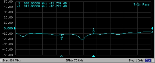
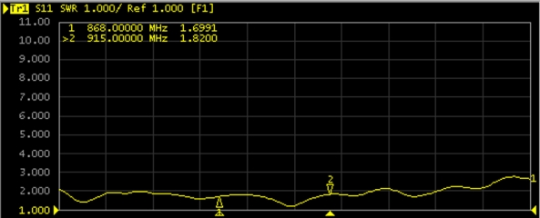
2. Voltage Standing Wave Ratio (VSWR)
When the input impedance of the antenna does not match the characteristic impedance of the transmission line (i.e., mismatch occurs), part of the input power is reflected back. The voltage standing wave ratio (VSWR) is an important parameter that reflects the relationship between incident power and reflected power.
VSWR is related to the antenna input impedance. In some cases, return loss (RL) or reflection coefficient (Γ) is used instead; all three describe the same characteristic. Their relationships are as follows:
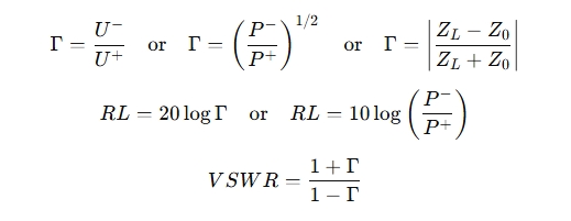
Where:
(P^-) is the reflected power
(P^+) is the incident power
(Z_L) is the antenna input impedance
(Z_0) is the characteristic impedance of the transmission line
(U^+) is the incident voltage
(U^-) is the reflected voltage
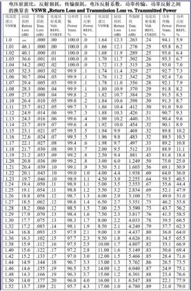
3. Logarithmic Conversion Relationships among Return Loss, VSWR, and Reflection Coefficient
Return loss, VSWR, and reflection coefficient are different representations of impedance matching performance and can be converted logarithmically using the above formulas.
4. Input Impedance
Input impedance is the impedance presented at the antenna input terminals. The antenna input impedance should be matched to the characteristic impedance of the transmission line and connectors. For mobile communication base station antennas, the nominal input impedance is typically 50 Ω, which means the characteristic impedance of the transmission line and connectors should also be 50 Ω.
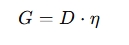
5. Gain
Antenna gain represents the combined effect of radiation directivity and energy conversion efficiency. It is determined by two main factors: radiation directivity and radiation efficiency.
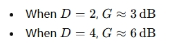
Gain is usually expressed in decibels (dB). Decibels are a logarithmic representation of a ratio:
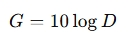
For example:
The unit dBi represents gain relative to an ideal isotropic radiator. In some cases, dBd is used, which represents gain relative to a half-wave dipole. The conversion relationship is:

For example:

6. Radiation Pattern
The radiation pattern is a graphical representation of how the radiated power density or field strength varies with spatial direction. Radiation patterns include horizontal-plane patterns and vertical-plane patterns.
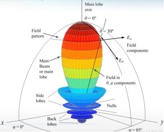
Many antenna characteristics can be observed from the radiation pattern, such as whether the antenna is omnidirectional or directional, beamwidth, downtilt angle, null filling, and sidelobe suppression. To enhance radiation performance, radiation pattern optimization is an important part of antenna design.
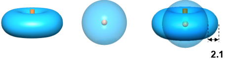
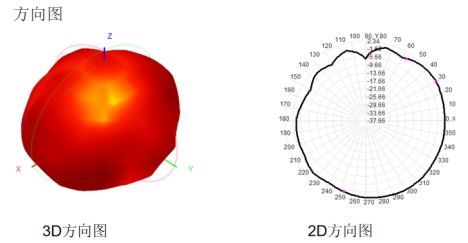
A 3D radiation pattern illustrates the overall signal distribution in space and allows observation of signal strength in all directions.
A 2D radiation pattern is typically obtained by slicing the 3D pattern along the XY, YZ, and XZ planes, providing quantitative evaluation of signal strength distribution in these planes.
Related Recommendations